Mitsubishi Outlander: Symptom Procedures (Central Door Locking System)
INSPECTION PROCEDURE A-1: Central Door Locking System does not Work at All.
CAUTION Before replacing the ECU, ensure that the power supply circuit, the ground circuit and the communication circuit are normal.
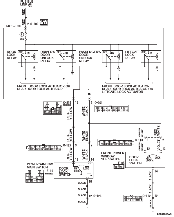
Central Door Lock Power Supply Circuit
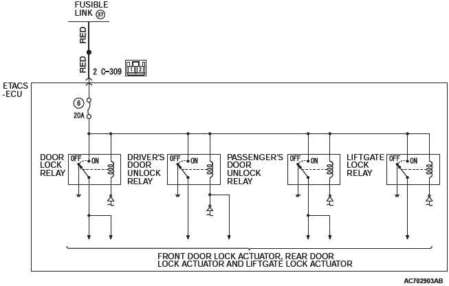
CIRCUIT OPERATION
- The ETACS-ECU controls the central door lock
system, locking or unlocking all the doors by activating
the central door lock relay (built into the
ETACS-ECU). The ETACS-ECU uses inputs from
the following components:
- Door lock actuators
- Door lock key cylinder switch
- Door lock switch, which is incorporated in the power window main switch or front power window sub switch
TROUBLESHOOTING HINTS
- The wiring harness or connectors may have loose, corroded, or damaged terminals, or terminals pushed back in the connector
- The ETACS-ECU may be defective
DIAGNOSTIC PROCEDURE
Required Special Tools:
- MB991223: Harness Set
- MB992006: Extra Fine Probe
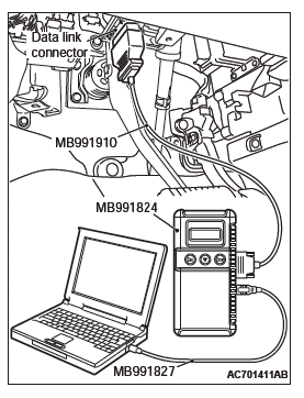
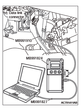
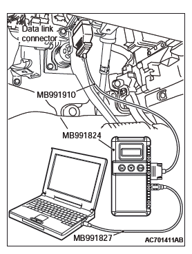
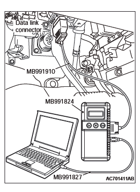
- MB991958: Scan Tool (M.U.T.-III Sub Assembly)
- MB991824: Vehicles Communication Interface (V.C.I.)
- MB991827: M.U.T.-III USB Cable
- MB991910: M.U.T.-III Main Harness A
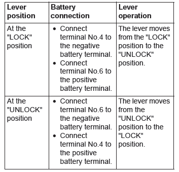
STEP 1. Using scan tool MB991958, check data list.
Check the input signals from the front door lock actuators.
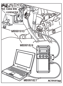
CAUTION To prevent damage to scan tool MB991958, always turn the ignition switch to the "LOCK" (OFF) position before connecting or disconnecting scan tool MB991958.
- Connect scan tool MB991958. Refer to GROUP 42B, Diagnosis "How to connect the Scan Tool (M.U.T.-III)".
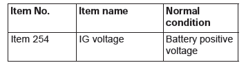
- Turn the ignition switch to the "ON" position.
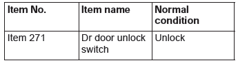
- Check the ETACS data list.
- Set the driver's door to "UNLOCK".
- Set the front passenger's door to "UNLOCK". <Vehicles with KOS>
- Turn the ignition switch to the "LOCK" (OFF) position.
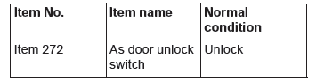
Q: Are normal conditions displayed on the "Dr door unlock switch" and "As door unlock switch"?
YES : Go to Step 2.
NO : Refer to GROUP 54A, Inspection Procedure 4: ETACS-ECU does not receive any signal from the front door lock actuator.
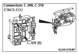
STEP 2. Check ETACS-ECU connector C-309 for loose, corroded or damaged terminals, or terminals pushed back in the connector.
Q: Is ETACS-ECU connector C-309 in good condition?
YES : Go to Step 3.
NO : Repair or replace the damaged component(s). Refer to GROUP 00E, Harness Connector Inspection. Verify that the central door locking system works normally.
STEP 3. Check the wiring harness between ETACS-ECU connector C-309 (terminal 2) and fusible link (37).
- Check the power supply line for open circuit and short circuit.
Q: Is the wiring harness between ETACS-ECU connector C-309 (terminal 2) and fusible link (37) in good condition?
YES : Go to Step 4.
NO : The wiring harness may be damaged or the connector may have loose, corroded or damaged terminals, or terminals pushed back in the connector. Repair the wiring harness as necessary. Verify that the central door locking system works normally.
STEP 4. Retest the system.
Check that the central door locking system works normally.
Q: Is the check result normal?
YES : No action is necessary and testing is complete.
NO : Replace the ETACS-ECU. Check that the central door locking system works normally.
INSPECTION PROCEDURE A-2: Central Door Locking System does not Operate even when Door Lock Switch of Power Window Main Switch Operated (Door Lock Switch of Front Power Window Sub Switch Operates Normally).
CAUTION Before replacing the ECU, ensure that the power supply circuit, the ground circuit and the communication circuit are normal.
Central Door Lock Power Supply Circuit
CIRCUIT OPERATION
- The ETACS-ECU controls the central door locking
system, locking or unlocking all doors by activating
the central door lock relay (built into the
ETACS-ECU). The ETACS-ECU uses inputs from
the following components:
- Door lock actuators
- Door lock switch, which is incorporated in the power window main switch or front power window sub switch
TROUBLESHOOTING HINTS
- The wiring harness or connectors may have loose, corroded, or damaged terminals, or terminals pushed back in the connector
- The power window main switch may be defective
DIAGNOSTIC PROCEDURE
STEP 1. Checking central door unlocking operation
Check that the central door locking system works normally.
Q: Is the check result normal?
YES : Go to Step 2.
NO : Refer to Inspection procedure A-1 "Central door locking system does not work at all P.42A".
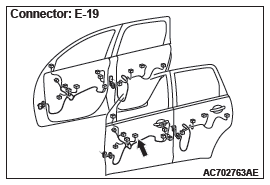
STEP 2. Check power window main switch connector E-19 for loose, corroded or damaged terminals, or terminals pushed back in the connector.
Q: Is power window main switch connector E-19 in good condition?
YES : Go to Step 3.
NO : Repair or check the connector. Refer to GROUP 00E, Harness Connector Inspection. Verify that all the doors can be locked and unlocked normally.
STEP 3. Check the power window main switch (door lock switch).
Remove the power window main switch.
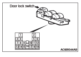

Q: Does the power window main switch work normally? YES : Go to Step 4.
NO : Replace the power window main switch. Verify that all the doors can be locked and unlocked normally.
STEP 4. Check the wiring harness between power window main switch connector E-19 (terminal No. 10) and ground.
- Check the ground line for open circuit.
NOTE: Also check intermediate connector C-126 for loose, corroded, or damaged terminals, or terminals pushed back in the connector. If intermediate connector C-126 is damaged, repair or replace the damaged component(s) as described in GROUP 00E, Harness Connector Inspection.
Q: Is the wiring harness between power window main switch connector E-19 (terminal No. 10) and ground in good condition?
YES : Go to Step 5.
NO : The wiring harness may be damaged or the connector(s) may have loose, corroded or damaged terminals, or terminals pushed back in the connector.
Repair the wiring harness as necessary.
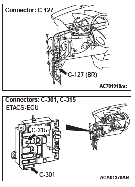
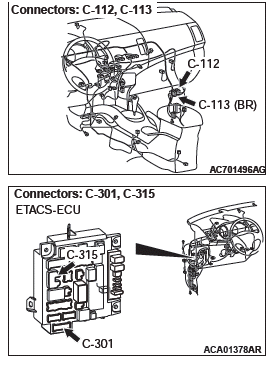
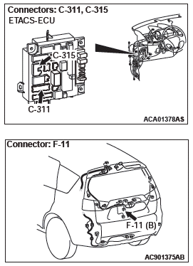
STEP 5. Check ETACS-ECU connector C-301, C-315 for loose, corroded or damaged terminals, or terminals pushed back in the connector.
Q: Are ETACS-ECU connector C-301, C-315 in good condition?
YES : Go to Step 6.
NO : Repair or replace the damaged component(s). Refer to GROUP 00E, Harness Connector Inspection. Check that the sunroof works normally.
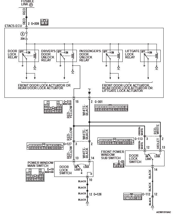
STEP 6. Check the wiring harness between power window main switch connector E-19 (terminal No. 13) and ETACS-ECU connector C-315 (terminal No. 15), between power window main switch connector E-19 (terminal No.14) and ETACS-ECU connector C-301 (terminal No. 2).
- Check the power supply line for open.
NOTE: Also check intermediate connector C-127 for loose, corroded, or damaged terminals, or terminals pushed back in the connector. If intermediate connector C-127 is damaged, repair or replace the damaged component(s) as described in GROUP 00E, Harness Connector Inspection.
Q: Are the wiring harness between power window main switch connector E-19 (terminal No. 13) and ETACS-ECU connector C-315 (terminal No. 15), between power window main switch connector E-19 (terminal No. 14) and ETACS-ECU connector C-301 (terminal No.2) in good condition?
YES : Go to Step 7.
NO : The wiring harness may be damaged or the connector may have loose, corroded or damaged terminals, or terminals pushed back in the connector. Repair the wiring harness as necessary. Verify that the central door locking system works normally.
STEP 7. Retest the system.
Check that the central door locking system works normally.
Q: Is the check result normal?
YES : No action is necessary and testing is complete.
NO : Replace the power window main switch. Check that the central door locking system normally.
INSPECTION PROCEDURE A-3: Central Door Locking System does not Operate even when Door Lock Switch of Front Power Window Sub Switch Operated (Door Lock Switch of Power Window Main Switch Operates Normally).
CAUTION Before replacing the ECU, ensure that the power supply circuit, the ground circuit and the communication circuit are normal.
Central Door Lock Power Supply Circuit
CIRCUIT OPERATION
- The ETACS-ECU controls the central door locking
system, locking or unlocking all doors by activating
the central door lock relay (built into the
ETACS-ECU). The ETACS-ECU uses inputs from
the following components:
- Door lock actuators
- Door lock switch, which is incorporated in the power window main switch or front power window sub switch
TROUBLESHOOTING HINTS
- The wiring harness or connectors may have loose, corroded, or damaged terminals, or terminals pushed back in the connector
- The front power window sub switch may be defective
DIAGNOSTIC PROCEDURE
STEP 1. Checking central door unlocking operation
Check that the central door locking system works normally.
Q: Is the check result normal?
YES : Go to Step 2.
NO : Refer to Inspection procedure A-1 "Central door locking system does not work at all P.42A".
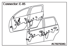
STEP 2. Check front power window sub switch connector E-05 for loose, corroded or damaged terminals, or terminals pushed back in the connector.
Q: Is front power window sub switch connector E-05 in good condition?
YES : Go to Step 3.
NO : Repair or check the connector. Refer to GROUP 00E, Harness Connector Inspection. Verify that all the doors can be locked and unlocked normally.
STEP 3. Check the front power window sub switch (door lock switch).
Remove the front power window sub switch.
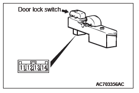
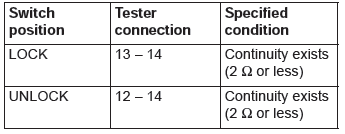
Q: Does the front power window sub switch work normally?
YES : Go to Step 4.
NO : Replace the front power window sub switch. Verify that all the doors can be locked and unlocked normally.
STEP 4. Check the ground circuit to the front power window sub switch. Measure the resistance at front power window sub switch connector E-05.
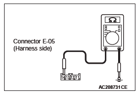
- Disconnect front power window sub switch connector E-05 and measure the resistance available at the wiring harness side of the connector.
- Measure the resistance value between terminal 14 and
ground.
- The resistance should be 2 ohms or less.
Q: Is the measured resistance 2 ohms or less?
YES : Go to Step 6.
NO : Go to Step 5.
STEP 5. Check the wiring harness between front power window sub switch connector E-05 (terminal No. 14) and ground.
- Check the ground line for open circuit.
NOTE: Also check intermediate connector C-112 for loose, corroded, or damaged terminals, or terminals pushed back in the connector. If intermediate connector C-112 is damaged, repair or replace the damaged component(s) as described in GROUP 00E, Harness Connector Inspection.
Q: Is the wiring harness between front power window sub switch connector E-05 (terminal No. 14) and ground in good condition?
YES : Go to Step 6.
NO : The wiring harness may be damaged or the connector(s) may have loose, corroded or damaged terminals, or terminals pushed back in the connector.
Repair the wiring harness as necessary.
STEP 6. Check ETACS-ECU connector C-301, C-315 for loose, corroded or damaged terminals, or terminals pushed back in the connector.
Q: Are ETACS-ECU connector C-301, C-315 in good condition?
YES : Go to Step 7.
NO : Repair or replace the damaged component(s). Refer to GROUP 00E, Harness Connector Inspection. Check that the sunroof works normally.
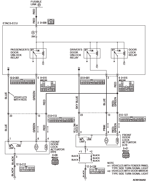
STEP 7. Check the wiring harness between power window sub switch connector E-05 (terminal No. 12) and ETACS-ECU connector C-315 (terminal No. 15), between power window sub switch connector E-05 (terminal No. 13) and ETACS-ECU connector C-301 (terminal No. 2).
- Check the power supply line for open circuit.
NOTE: Also check intermediate connector C-113 for loose, corroded, or damaged terminals, or terminals pushed back in the connector. If intermediate connector C-113 is damaged, repair or replace the damaged component(s) as described in GROUP 00E, Harness Connector Inspection.
Q: Are the wiring harness between power window sub switch connector E-05 (terminal No. 12) and ETACS-ECU connector C-315 (terminal No. 15), between power window sub switch connector E-05 (terminal No.13) and ETACS-ECU connector C-301 (terminal No. 2) in good condition?
YES : Go to Step 8.
NO : The wiring harness may be damaged or the connector may have loose, corroded or damaged terminals, or terminals pushed back in the connector. Repair the wiring harness as necessary. Verify that the central door locking system works normally.
STEP 8. Retest the system.
Check that the central door locking system works normally.
Q: Is the check result normal?
YES : No action is necessary and testing is complete.
NO : Replace the front power window sub switch. Check that the central door locking system normally.
INSPECTION PROCEDURE A-4: A Door or a Liftgate cannot be Locked or Unlocked by the Central Door Locking System.
CAUTION Before replacing the ECU, ensure that the power supply circuit, the ground circuit and the communication circuit are normal.
Central Door Lock Circuit <Front Door>
Central Door Lock Circuit <Rear Door and Liftgate>
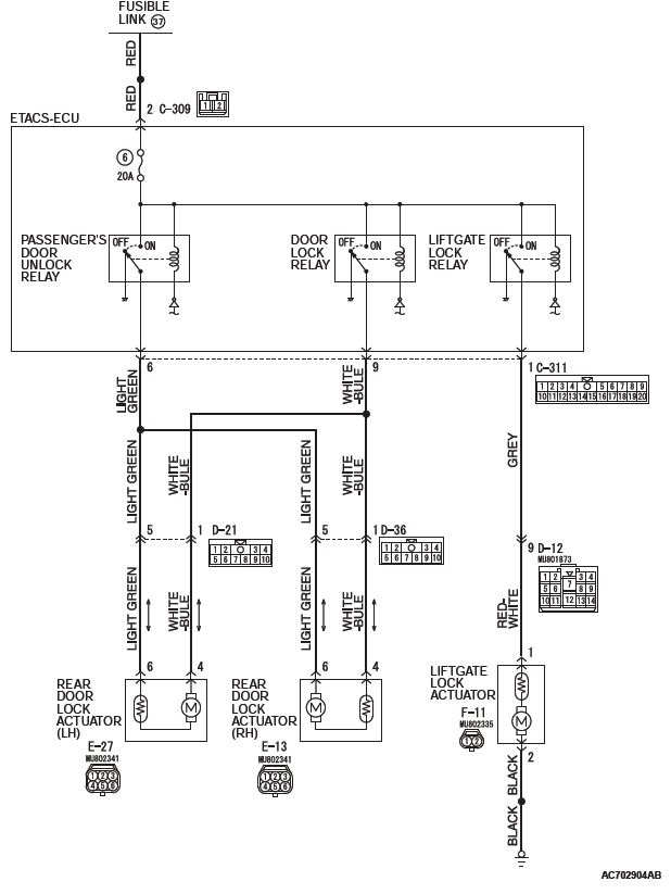
CIRCUIT OPERATION
- The ETACS-ECU operates the central door locking
system according to the following signals:
- Door lock actuator switch
- Door lock key cylinder switch
- Door lock switch, which is incorporated in the power window main switch or front power window sub switch
- The ETACS-ECU locks or unlocks all doors by operating the central door lock relay (incorporated in the ECU) in response to input signals.
TECHNICAL DESCRIPTION (COMMENT)
The wiring harness between the ETACS-ECU and the door lock actuator may be defective.
TROUBLESHOOTING HINTS
- The door lock actuator may be defective
- The liftgate lock actuator may be defective
- The wiring harness or connectors may have loose, corroded, or damaged terminals, or terminals pushed back in the connector
- The ETACS-ECU may be defective
DIAGNOSTIC PROCEDURE
STEP 1. Confirmation of the defective door lock actuator or liftgate lock actuator.
Q: Which door or liftgate is not operating normally?
Driver's door : Go to Step 2.
Front passenger's door : Go to Step 6.
Rear right door : Go to Step 10.
Rear left door : Go to Step 14.
Liftgate : Go to Step 18.
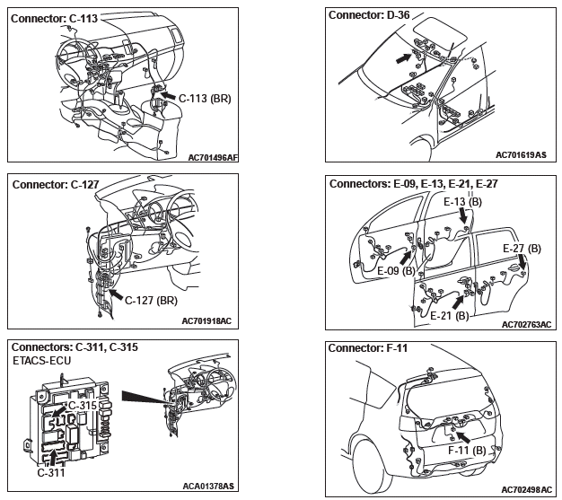
STEP 2. Check front door lock actuator (LH) connector E-21 for loose, corroded or damaged terminals, or terminals pushed back in the connector.
Q: Is the front door lock actuator (LH) connector E-21 in good condition?
YES : Go to Step 3.
NO : Repair or check the connector. Refer to GROUP 00E, Harness Connector Inspection. Verify that all the doors and the liftgate can be locked and unlocked normally.
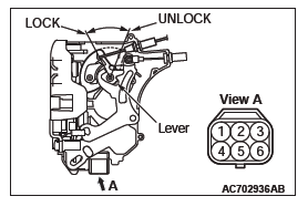
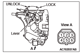
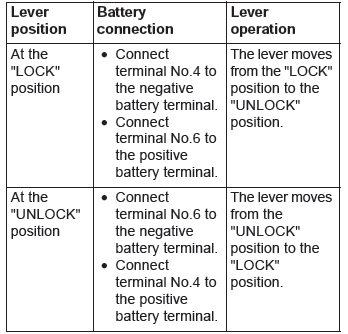
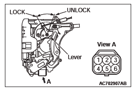
STEP 3. Check the front door lock actuator (LH).
Remove the front door lock actuator (LH). The illustration shows when the door lock actuator is viewed from inside the door.

Q: Does the front door lock actuator (LH) work normally?
YES : Go to Step 4.
NO : Replace the front door lock actuator (LH). Verify that all the doors and the liftgate can be locked and unlocked normally.
STEP 4. Check ETACS-ECU connector C-315 for loose, corroded or damaged terminals, or terminals pushed back in the connector.
Q: Is ETACS-ECU connector C-315 in good condition?
YES : Go to Step 5.
NO : Repair or check the connector. Refer to GROUP 00E, Harness Connector Inspection. Verify that all the doors and the liftgate can be locked and unlocked normally.
STEP 5. Check the wiring harness between ETACS-ECU connector C-315 (terminals No. 2 and 6) and front door lock actuator (LH) connector E-21 (terminals No. 6 and 4).
- Check the power supply line for open circuit and short circuit.
NOTE: Also check intermediate connector C-127 for loose, corroded, or damaged terminals, or terminals pushed back in the connector. If intermediate connector C-127 is damaged, repair or replace the damaged component(s) as described in GROUP 00E, Harness Connector Inspection.
Q: Is the wiring harness between ETACS-ECU connector C-315 (terminals No. 2 and 6) and front door lock actuator (LH) connector E-21 (terminals No. 6 and 4) in good condition?
YES : Go to Step 24.
NO : The wiring harness may be damaged or the connector(s) may have loose, corroded or damaged terminals, or terminals pushed back in the connector.
Repair or replace the damaged component(s). Verify that all the doors and the liftgate can be locked and unlocked normally.
STEP 6. Check front door lock actuator (RH) connector E-09 for loose, corroded or damaged terminals, or terminals pushed back in the connector.
Q: Is front door lock actuator (RH) connector E-09 in good condition?
YES : Go to Step 7.
NO : Repair or replace the damaged component(s). Refer to GROUP 00E, Harness Connector Inspection. Verify that all the doors and the liftgate can be locked and unlocked normally.
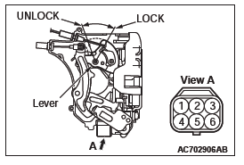
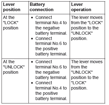
STEP 7. Check the front door lock actuator (RH).
Remove the front door lock actuator (RH). The illustration shows when the door lock actuator is viewed from inside the door.
Q: Is the front door lock actuator (RH) normal?
YES : Go to Step 8.
NO : Replace the front door lock actuator (RH). Verify that all the doors and the liftgate can be locked and unlocked normally.
STEP 8. Check ETACS-ECU connector C-315 for loose, corroded or damaged terminals, or terminals pushed back in the connector.
Q: Is ETACS-ECU connector C-315 in good condition?
YES : Go to Step 9.
NO : Repair or replace the damaged component(s). Refer to GROUP 00E, Harness Connector Inspection. Verify that all the doors and the liftgate can be locked and unlocked normally.
STEP 9. Check the wiring harness between ETACS-ECU connector C-315 (terminals No. 5 and 6) and front door lock actuator (RH) connector E-09 (terminals No. 6 and 4).
- Check the power supply line for open circuit and short circuit.
NOTE: Also check intermediate connector C-113 for loose, corroded, or damaged terminals, or terminals pushed back in the connector. If intermediate connector C-113 is damaged, repair or replace the damaged component(s) as described in GROUP 00E, Harness Connector Inspection.
Q: Is the wiring harness between ETACS-ECU connector C-315 (terminals No. 5 and 6) and front door lock actuator (RH) connector E-09 (terminals No. 6 and 4) in good condition?
YES : Go to Step 24.
NO : The wiring harness may be damaged or the connector(s) may have loose, corroded or damaged terminals, or terminals pushed back in the connector.
Repair the wiring harness as necessary. Verify that all the doors and the liftgate can be locked and unlocked normally.
STEP 10. Check rear door lock actuator (RH) connector E-13 for loose, corroded or damaged terminals, or terminals pushed back in the connector.
Q: Is rear door lock actuator (RH) connector E-13 in good condition?
YES : Go to Step 11.
NO : Repair or check the connector. Refer to GROUP 00E, Harness Connector Inspection. Verify that all the doors can be locked and unlocked normally.
STEP 11. Check the rear door lock actuator (RH).
Remove the rear door lock actuator (RH). The illustration shows when the door lock actuator is viewed from inside the door.
Q: Is the rear door lock actuator (RH) normal?
YES : Go to Step 12.
NO : Replace the rear door lock actuator (RH). Verify that all the doors and the liftgate can be locked and unlocked normally.
STEP 12. Check ETACS-ECU connector C-311 for loose, corroded or damaged terminals, or terminals pushed back in the connector.
Q: Is ETACS-ECU connector C-311 in good condition?
YES : Go to Step 13.
NO : Repair or replace the damaged component(s). Refer to GROUP 00E, Harness Connector Inspection. Verify that all the doors and the liftgate can be locked and unlocked normally.
STEP 13. Check the wiring harness between ETACS-ECU connector C-311 (terminals No. 6 and 9) and rear door lock actuator (RH) connector E-13 (terminals No. 6 and 4).
- Check the power supply line for open circuit and short circuit.
NOTE: Also check intermediate connector D-36 for loose, corroded, or damaged terminals, or terminals pushed back in the connector. If intermediate connector D-36 is damaged, repair or replace the damaged component(s) as described in GROUP 00E, Harness Connector Inspection.
Q: Is the wiring harness between ETACS-ECU connector C-311 (terminals No. 6 and 9) and rear door lock actuator (RH) connector E-13 (terminals No. 6 and 4) in good condition?
YES : Go to Step 24.
NO : The wiring harness may be damaged or the connector(s) may have loose, corroded or damaged terminals, or terminals pushed back in the connector.
Repair the wiring harness as necessary. Verify that all the doors and the liftgate can be locked and unlocked normally.
STEP 14. Check rear door lock actuator (LH) connector E-27 for loose, corroded or damaged terminals, or terminals pushed back in the connector.
Q: Is rear door lock actuator (LH) connector E-27 in good condition?
YES : Go to Step 15.
NO : Repair or check the connector. Refer to GROUP 00E, Harness Connector Inspection. Verify that all the doors and the liftgate can be locked and unlocked normally.
STEP 15. Check the rear door lock actuator (LH).
Remove the rear door lock actuator (LH). The illustration shows when the door lock actuator is viewed from inside the door.
Q: Is the rear door lock actuator (LH) normal?
YES : Go to Step 16.
NO : Replace the rear door lock actuator (LH). Verify that all the doors and the liftgate can be locked and unlocked normally.
STEP 16. Check ETACS-ECU connector C-311 for loose, corroded or damaged terminals, or terminals pushed back in the connector.
Q: Is ETACS-ECU connector C-311 in good condition?
YES : Go to Step 17.
NO : Repair or replace the damaged component(s). Refer to GROUP 00E, Harness Connector Inspection. Verify that all the doors and the liftgate can be locked and unlocked normally.
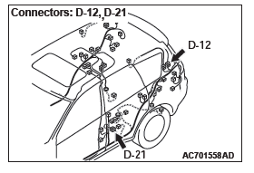
STEP 17. Check the wiring harness between ETACS-ECU connector C-311 (terminals No. 6 and 9) and rear door lock actuator (LH) connector E-27 (terminals No. 6 and 4).
- Check the power supply line for open circuit and short circuit.
NOTE: Also check intermediate connector D-21 for loose, corroded, or damaged terminals, or terminals pushed back in the connector. If intermediate connector D-21 is damaged, repair or replace the damaged component(s) as described in GROUP 00E, Harness Connector Inspection.
Q: Is the wiring harness between ETACS-ECU connector C-311 (terminals No. 6 and 9) and rear door lock actuator (LH) connector E-27 (terminals No. 6 and 4) in good condition?
YES : Go to Step 24.
NO : The wiring harness may be damaged or the connector(s) may have loose, corroded or damaged terminals, or terminals pushed back in the connector.
Repair the wiring harness as necessary. Verify that all the doors and the liftgate can be locked and unlocked normally.
STEP 18. Check liftgate lock actuator connector F-11 for loose, corroded or damaged terminals, or terminals pushed back in the connector.
Q: Is liftgate lock actuator connector F-11 in good condition?
YES : Go to Step 19.
NO : Repair or check the connector. Refer to GROUP 00E, Harness Connector Inspection. Verify that all the doors and the liftgate can be locked and unlocked normally.
STEP 19. Check the liftgate lock actuator.
Remove the liftgate lock actuator. The illustration shows when the liftgate lock actuator is viewed from inside the liftgate. Refer to GROUP 42A, Liftgate Handle and Latch.
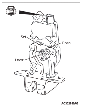

Q: Is the liftgate lock actuator normal?
YES : Go to Step 20.
NO : Replace the liftgate lock actuator. Verify that all the doors and the liftgate can be locked and unlocked normally.
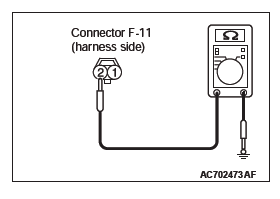
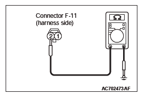
STEP 20. Check the ground circuit to the liftgate lock actuator. Measure the resistance at liftgate lock actuator connector F-11.
- Disconnect liftgate lock actuator connector F-11 and measure the resistance on the wiring harness side of the connector.
- Measure the resistance value between terminal 2 and
ground.
- The resistance should be 2 ohms or less.
Q: Is the measured resistance 2 ohms or less?
YES : Go to Step 22.
NO : Go to Step 21.
STEP 21. Check the wiring harness between liftgate lock actuator connector F-11 (terminal No. 2) and ground.
- Check the ground line for open circuit.
Q: Is the wiring harness between liftgate lock actuator connector F-11 (terminal No. 2) and ground in good condition?
YES : No action is necessary and testing is complete.
NO : The wiring harness may be damaged or the connector(s) may have loose, corroded or damaged terminals, or terminals pushed back in the connector.
Repair the wiring harness as necessary. Verify that all the doors and the liftgate can be locked and unlocked normally.
STEP 22. Check ETACS-ECU connector C-311 for loose, corroded or damaged terminals, or terminals pushed back in the connector.
Q: Is ETACS-ECU connector C-311 in good condition?
YES : Go to Step 23.
NO : Repair or replace the damaged component(s). Refer to GROUP 00E, Harness Connector Inspection. Verify that all the doors and the liftgate can be locked and unlocked normally.
STEP 23. Check the wiring harness between ETACS-ECU connector C-311 (terminal No. 1) and liftgate lock actuator connector F-11 (terminal No. 1).
- Check the power supply line for open circuit and short circuit.
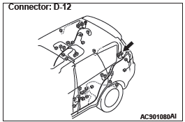
NOTE: Also check intermediate connector D-12 for loose, corroded, or damaged terminals, or terminals pushed back in the connector. If intermediate connector D-12 is damaged, repair or replace the damaged component(s) as described in GROUP 00E, Harness Connector Inspection.
Q: Is the wiring harness between ETACS-ECU connector C-311 (terminal No. 1) and liftgate lock actuator connector F-11 (terminal No. 1) in good condition?
YES : Go to Step 24.
NO : The wiring harness may be damaged or the connector(s) may have loose, corroded or damaged terminals, or terminals pushed back in the connector.
Repair the wiring harness as necessary. Verify that all the doors and the liftgate can be locked and unlocked normally.
STEP 24. Retest the system.
Check that the central door locking system works normally.
Q: Is the check result normal?
YES : No action is necessary and testing is complete.
NO : Replace the ETACS-ECU. Check that the central door locking system normally.
INSPECTION PROCEDURE A-5: The Liftgate does not Open.
CAUTION Before replacing the ECU, ensure that the input and output signal circuits are normal.
Liftgate Open Circuit
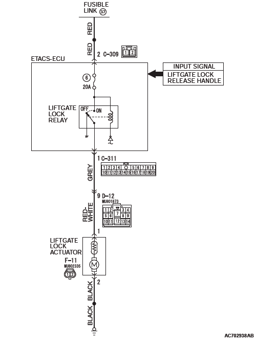
CIRCUIT OPERATION
The ETACS-ECU operates this function in accordance with the input signals below.
- Vehicle speed signal (ASC-ECU)
- Liftgate lock release handle
- Liftgate lock actuator
TECHNICAL DESCRIPTION (COMMENT)
If this function does not work normally, a malfunction of the input signal circuit(s) or ETACS-ECU is suspected.
TROUBLESHOOTING HINTS
- Vehicle speed signal ((ASC-ECU) error
- Malfunction of the liftgate lock release handle
- Malfunction of the liftgate lock actuator
- Malfunction of ETACS-ECU
- Damaged wiring harness and connectors
DIAGNOSTIC PROCEDURE
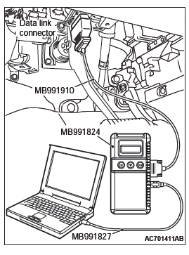
Required Special Tools:
- MB991223: Harness Set
- MB992006: Extra Fine Probe
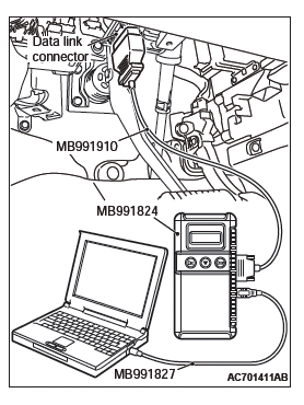
- MB991958: Scan Tool (M.U.T.-III Sub Assembly)
- MB991824: Vehicles Communication Interface (V.C.I.)
- MB991827: M.U.T.-III USB Cable
- MB991910: M.U.T.-III Main Harness A
STEP 1. Checking central door unlocking operation
Check that the central door locking system works normally.
Q: Is the check result normal?
YES : Go to Step 2.
NO : Refer to P.42A.
STEP 2. Using scan tool MB991958, read the CAN bus diagnostic trouble code.
CAUTION To prevent damage to scan tool MB991958, always turn the ignition switch to the "LOCK" (OFF) position before connecting or disconnecting scan tool MB991958.
- Connect scan tool MB991958. Refer to GROUP 42B, "How to connect scan tool (M.U.T.-III)".
- Turn the ignition switch to the "ON" position.
- Check whether the CAN bus lines related DTC is set.
- Turn the ignition switch to the "LOCK" (OFF) position.
Q: Is the DTC set?
YES : Repair the CAN bus line (Refer to GROUP 54C, CAN bus diagnostics table).
NO : Go to Step 3.
STEP 3. Using scan tool MB991958, read the ASC-ECU diagnostic trouble code.
CAUTION To prevent damage to scan tool MB991958, always turn the ignition switch to the "LOCK" (OFF) position before connecting or disconnecting scan tool MB991958.
- Connect scan tool MB991958. Refer to GROUP 42B, "How to connect scan tool (M.U.T.-III)".
- Turn the ignition switch to the "ON" position.
- Check that the ASC-ECU sets a diagnostic trouble code.
- Turn the ignition switch to the "LOCK" (OFF) position.
Q: Is the DTC set?
YES : Diagnose ASC-ECU (Refer to GROUP 35C, Diagnostic Trouble Code Chart).
NO : Go to Step 4.
STEP 4. Using scan tool MB991958, check data list.
Check the input signals from the liftgate lock release handle.

CAUTION To prevent damage to scan tool MB991958, always turn the ignition switch to the "LOCK" (OFF) position before connecting or disconnecting scan tool MB991958.
- Connect scan tool MB991958. Refer to GROUP 42B, "How to connect scan tool (M.U.T.-III)".
- Turn the ignition switch to the "ON" position.
- Check the data list of the ETACS.
- Liftgate lock release handle: from OFF to ON
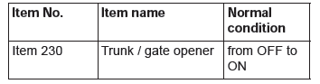
- Turn the ignition switch to the "LOCK" (OFF) position.
OK: Normal condition is displayed.
Q: Is the check result normal?
YES : Go to Step 5.
NO : Refer to P.42A.
STEP 5. Check ETACS-ECU connector C-311 for loose, corroded or damaged terminals, or terminals pushed back in the connector.
Q: Is ETACS-ECU connector C-311 in good condition?
YES : Go to Step 6.
NO : Repair or replace the damaged component(s). Refer to GROUP 00E, Harness Connector Inspection. Verify that the liftgate can be locked and unlocked normally.
STEP 6. Check the liftgate lock actuator.
Remove the liftgate lock actuator. The illustration shows when the liftgate lock actuator is viewed from inside the liftgate. Refer to GROUP 42A, Liftgate Handle and Latch <Liftgate upper>.
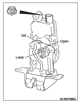
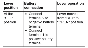
Q: Is the liftgate lock actuator normal?
YES : Go to Step 7.
NO : Replace the liftgate lock actuator. Verify that the liftgate can be locked and unlocked normally.
STEP 7. Check the ground circuit to the liftgate lock actuator. Measure the resistance at liftgate lock actuator connector F-11.
- Disconnect liftgate lock actuator connector F-11 and measure the resistance on the wiring harness side of the connector.
- Measure the resistance value between terminal 2 and ground.
- The resistance should be 2 ohms or less.
Q: Is the measured resistance 2 ohms or less?
YES : Go to Step 9.
NO : Go to Step 8.
STEP 8. Check the wiring harness between liftgate lock actuator connector F-11 (terminal 2) and ground.
- Check the power supply line for open circuit and short circuit.
Q: Is the wiring harness between liftgate lock actuator connector F-11 (terminal 2) and ground in good condition?
YES : No action is necessary and testing is complete.
NO : The wiring harness may be damaged or the connector(s) may have loose, corroded or damaged terminals, or terminals pushed back in the connector.
Repair the wiring harness as necessary. Verify that the liftgate can be locked and unlocked normally.
STEP 9. Check the wiring harness between ETACS-ECU connector C-311 (terminal 1) and liftgate lock actuator connector F-11 (terminal 1).
- Check the power supply line for open circuit and short circuit.
NOTE: Also check intermediate connector D-12 for loose, corroded, or damaged terminals, or terminals pushed back in the connector. If intermediate connector D-12 is damaged, repair or replace the damaged component(s) as described in GROUP 00E, Harness Connector Inspection.
Q: Is the wiring harness between ETACS-ECU connector C-311 (terminal 1) and liftgate lock actuator connector F-11 (terminal 1) in good condition?
YES : Go to Step 10.
NO : The wiring harness may be damaged or the connector(s) may have loose, corroded or damaged terminals, or terminals pushed back in the connector.
Repair the wiring harness as necessary. Verify that the liftgate can be locked and unlocked normally.
STEP 10. Retest the system.
Check that the liftgate can be locked and unlocked normally.
Q: Is the check result normal?
YES : No action is necessary and testing is complete.
NO : Replace the ETACS-ECU. Check that the liftgate can be locked and unlocked normally.
INSPECTION PROCEDURE A-6: Selector "P" Position-linked Door Unlock Function does not Operate.
CAUTION Before replacing the ECU, ensure that the power supply circuit, the ground circuit and the communication circuit are normal.
Selector "P" Position-linked Door Unlock Function
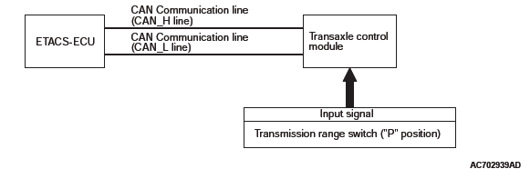
OPERATION
ETACS-ECU determines whether the shift position is "P" or not according to the shift position signal sent by transaxle control module.
TECHNICAL DESCRIPTION (COMMENT)
If the doors are not unlocked when the selector lever is shifted to the "P" position, a malfunction of the shift position signal input circuit(s) or ETACS-ECU is suspected.
Also, the selector "P" position-linked door unlock function may have been set to "Disabled" with the customization function.
TROUBLESHOOTING HINTS
- Malfunction of selector lever
- Malfunction of ETACS-ECU
- Damaged wiring harness and connectors
DIAGNOSTIC PROCEDURE
Required Special Tools:
- MB991223: Harness Set
- MB992006: Extra Fine Probe
- MB991958: Scan Tool (M.U.T.-III Sub Assembly)
- MB991824: Vehicles Communication Interface (V.C.I.)
- MB991827: M.U.T.-III USB Cable
- MB991910: M.U.T.-III Main Harness A
STEP 1. Checking central door unlocking operation
Check that the central door locking system works normally.
Q: Is the check result normal?
YES : Go to Step 2.
NO : Refer to P.42A.
STEP 2. Check the customization function.
Check that the following other than "Disabled" is set for "Auto door unlock by P position" with the customization function.
- Always (P pos)
Q: Is the check result normal?
YES : Go to Step 3.
NO : Set the function "Always (P pos)" for "Auto door unlock by P position" with the customization function.
STEP 3. Using scan tool MB991958, check CAN bus for diagnostic trouble code.
CAUTION To prevent damage to scan tool MB991958, always turn the ignition switch to the "LOCK" (OFF) position before connecting or disconnecting scan tool MB991958.
- Connect scan tool MB991958. Refer to GROUP 42B, "How to connect scan tool (M.U.T.-III)".
- Turn the ignition switch to the "ON" position.
- Check whether CAN bus lines related DTC is set.
- Turn the ignition switch to the "LOCK" (OFF) position.
Q: Is the DTC set?
YES : Repair the CAN bus line (Refer to GROUP 54C, CAN bus diagnostics table).
NO : Go to Step 4.
STEP 4. Using scan tool MB991958, read the diagnostic trouble code.
CAUTION To prevent damage to scan tool MB991958, always turn the ignition switch to the "LOCK" (OFF) position before connecting or disconnecting scan tool MB991958.
- Connect scan tool MB991958. Refer to GROUP 42B, "How to connect scan tool (M.U.T.-III)".
- Turn the ignition switch to the "ON" position.
- Check the transaxle control module for diagnostic trouble code.
- Turn the ignition switch to the "LOCK" (OFF) position.
Q: Is the DTC set?
YES <2.4L> : Diagnose transaxle control module.
YES <3.0L> : Diagnose transaxle control module.
NO : Go to Step 5.
STEP 5. Retest the system.
Check that shifting the selector lever to the "P" position unlocks the doors.
Q: Is the check result normal?
YES : No action is necessary and testing is complete.
NO : Replace the ETACS-ECU. Check that the selector lever to the P position unlocks the doors normally.
INSPECTION PROCEDURE A-7: Ignition "LOCK (OFF)" Position-linked Door Unlock Function does not Operate.
CAUTION Before replacing the ECU, ensure that the power supply circuit, the ground circuit and the communication circuit are normal.
TECHNICAL DESCRIPTION (COMMENT)
If a door is not unlocked when the ignition switch is turned to the LOCK position, a malfunction of the CAN bus line, ignition switch or ETACS-ECU is suspected.
Also, the ignition "LOCK" position-linked door unlock function may have been set to "Disabled" with the customization function.
TROUBLESHOOTING HINTS
- Malfunction of CAN bus line
- Malfunction of ETACS-ECU
- Malfunction of ignition switch
- Damaged wiring harness and connectors
DIAGNOSIS PROCEDURE
Required Special Tools:
- MB991223: Harness Set
- MB992006: Extra Fine Probe
- MB991958: Scan Tool (M.U.T.-III Sub Assembly)
- MB991824: Vehicles Communication Interface (V.C.I.)
- MB991827: M.U.T.-III USB Cable
- MB991910: M.U.T.-III Main Harness A
STEP 1. Checking central door unlocking operation
Check that the central door locking system works normally.
Q: Is the check result normal?
YES : Go to Step 2.
NO : Refer to trouble symptom chart.
STEP 2. Check the customization function.
Check that the following other than "Disabled" is set for "Auto door unlock by ignition LOCK position" with the customization function.
- Always (LOCK pos)
Q: Is the check result normal?
YES : Go to Step 3.
NO : Set the function "Always (LOCK pos)" for "Auto door unlock by ignition LOCK position" with the customization function.
STEP 3. Using scan tool MB991958, check CAN bus for diagnostic trouble code.
CAUTION To prevent damage to scan tool MB991958, always turn the ignition switch to the "LOCK" (OFF) position before connecting or disconnecting scan tool MB991958.
- Connect scan tool MB991958. Refer to GROUP 42B, "How to connect scan tool (M.U.T.-III)".
- Turn the ignition switch to the "ON" position.
- Check whether CAN bus lines related DTC is set.
- Turn the ignition switch to the "LOCK" (OFF) position.
Q: Is the DTC set?
YES : Repair the CAN bus line (Refer to GROUP 54C, CAN bus diagnostics table).
NO : Go to Step 4.
STEP 4. Using scan tool MB991958, read the diagnostic trouble code.
CAUTION To prevent damage to scan tool MB991958, always turn the ignition switch to the "LOCK" (OFF) position before connecting or disconnecting scan tool MB991958.
- Connect scan tool MB991958. Refer to GROUP 42B, "How to connect scan tool (M.U.T.-III)".
- Turn the ignition switch to the "ON" position.
- Check whether any DTC is set to ETACS-ECU.
- Turn the ignition switch to the "LOCK" (OFF) position.
Q: Is the DTC set?
YES : Diagnose the ETACS-ECU.
NO : Go to Step 5.
STEP 5. Using scan tool MB991958, check data list.
- Ignition switch: ON→LOCK(OFF)
OK: Normal condition is displayed.
Q: Is the check result normal?
YES : Go to Step 6.
NO : Refer to GROUP 54A − Inspection Procedure 2 "Defective power supply system of the ignition switch"
STEP 6. Retest the system.
Check that turning the ignition switch to the "LOCK" position unlocks the doors.
Q: Is the check result normal?
YES : No action is necessary and testing is complete.
NO : Replace the ETACS-ECU.
READ NEXT:
 Input Signal Procedures (Central Door Locking System)
INSPECTION PROCEDURE B-1: The Liftgate Lock Release Handle Signal is
not Received.
CAUTION
Before replacing the ECU, ensure that the power supply circuit, the ground
circuit and the communication
ci
Power Window Diagnosis
TROUBLESHOOTING STRATEGY
Refer to GROUP 00, How to Use Troubleshooting/Inspection
Service Points, Troubleshooting Contents.
DIAGNOSTIC TROUBLE CODE CHART POWER WINDOW
CAUTION
On troubleshooting, if th
Symptom Procedures (Power Window)
INSPECTION PROCEDURE C-1: Power Windows do not Work at All.
CAUTION
Before replacing the ECU, ensure that the power supply circuit, the ground
circuit and the communication
circuit are normal.
Power
SEE MORE:
Balancer Shaft and Oil Pump Module
REMOVAL AND INSTALLATION
Pre-removal and Post-installation Operation
Engine Oil Pan Removal and Installation
Removal steps
Balancer shaft and oil pump
module
Required Special Tool:
MB991614: Angle Gauge
REMOVAL SERVICE POINT
BALANCER SHAFT AND OIL PUMP MODULE
REMOVAL
CAUTION
Never turn
DTC U0020, U0021, U0022, U0023, U0024, U0025, U0026, U0141, U0151, U0155, U0164,
U0168, U0184, U0195, U0245, U1419, U141A, U141B, U141C, U1423
DTC U0020: CAN-B Bus Off Performance
DTC U0021: CAN-B Bus(H1) Circuit Open
DTC U0022: CAN-B Bus(H1) Shorted to Circuit Ground
DTC U0023: CAN-B Bus(H1) Shorted to Circuit Power Supply
DTC U0024: CAN-B Bus(L0) Circuit Open
DTC U0025: CAN-B Bus(L0) Shorted to Circuit Ground
DTC U0026: CAN-B Bus(L0) Sho
