Mitsubishi Outlander: DTC C100A, C1015, C1020, C102B, C1011, C101C, C1027, C1032, C1014, C101F, C102A, C1035
DTC C100A: Abnormality in FL wheel speed sensor circuit
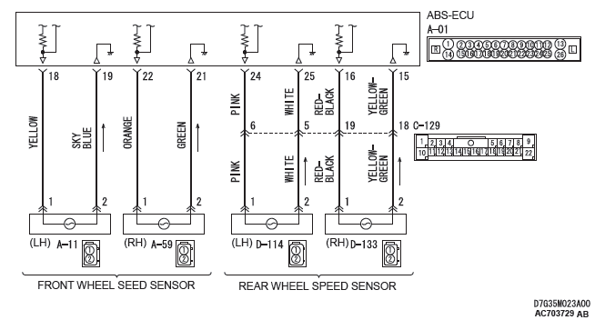
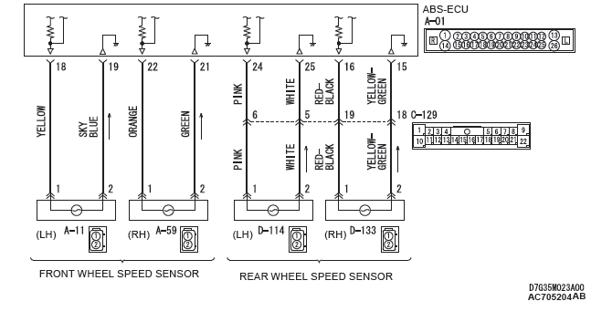
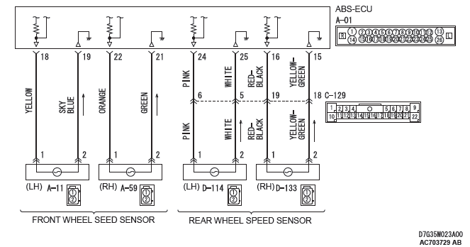
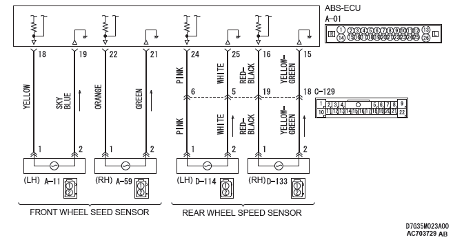
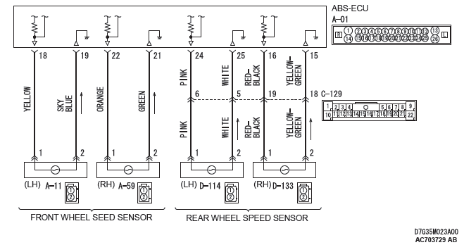
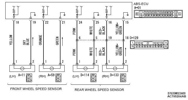
Wheel Speed Sensor Circuit
CAUTION
If there is any problem in the CAN bus lines, an incorrect DTC may be set. Prior to this diagnosis, diagnose the CAN bus lines.
CIRCUIT OPERATION
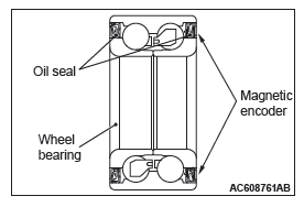
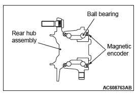
- The wheel speed sensor is a type of pulse generator. It consists of encoders (a plate on which north and south pole sides of the magnets are arranged alternately) for detecting the wheel speed which rotates at the same speed of the wheels and wheel speed sensors. This sensor outputs frequency pulse signals in proportion to the wheel speed.
- The pulse signals, which the wheel speed sensor creates, are sent to ABS-ECU. ABS-ECU uses the frequency of the pulse signals to determine the wheel speed.
DTC SET CONDITIONS
ABS-ECU monitors the voltage fluctuation in each wheel speed sensor circuit. If ABS-ECU detects the open or short circuit in the circuit, it will set a DTC.
PROBABLE CAUSES
Current trouble
- Damaged wiring harness and connectors
- Noise interference
- Malfunction of wheel speed sensor
- ABS-ECU malfunction
Past trouble
- Carry out diagnosis with particular emphasis on wiring harness and connector failures between ABS-ECU and the wheel speed sensor. For diagnosis procedures, refer to How to treat past trouble (GROUP 00 − How to Use Troubleshooting/ How to Treat Past Trouble).
DIAGNOSIS
Required Special Tools:
- MB991958: Scan Tool (M.U.T.-III Sub Assembly)
- MB991824: Vehicle Communication Interface (V.C.I.)
- MB991827: M.U.T.-III USB Cable
- MB991910: M.U.T.-III Main Harness A
- MB991974: ABS check harness
STEP 1. Using scan tool MB991958, diagnose the CAN bus line.
Use scan tool to diagnose the CAN bus lines.
Q: Is the check result normal?
YES : Go to Step 3.
NO : Repair the CAN bus lines (Refer to GROUP 54C − CAN Bus Diagnostics Table). On completion, go to Step 2.
STEP 2. DTC recheck after resetting CAN bus lines
Q: Is the DTC C100A set?
YES : Go to Step 3.
NO : The procedure is complete.
STEP 3. Scan tool data list
Check the following data list.
- Item No.01: FL wheel speed sensor
Q: Is the check result normal?
YES : Go to Step 12.
NO : Go to Step 4.
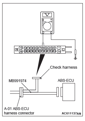
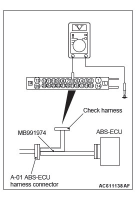
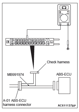
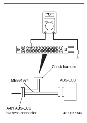
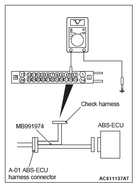
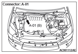
STEP 4. Voltage measurement at the A-01 ABS-ECU connector
- Disconnect the ABS-ECU connector, connect special tool ABS check harness (MB991974) to the harness-side connector, and then measure the voltage at the special tool connector side.
NOTE: Do not connect the special tool ABS check harness(MB991974) to ABS-ECU.
- Turn the ignition switch to the ON position.
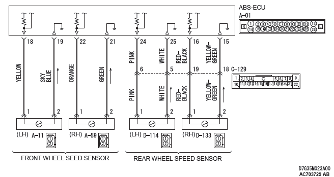
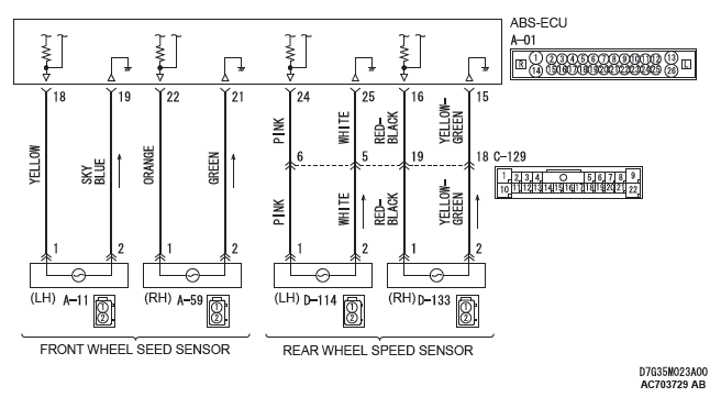
- Measure the voltage between the front wheel speed sensor <LH> power supply terminal (signal terminal) No.18 and body ground, and between the ground terminal No.19 and body ground.
OK: 1 volt or less
Q: Is the check result normal?
YES : Go to Step 5.
NO (Not normal at the terminal No.18 or 19) : Go to Step 6.
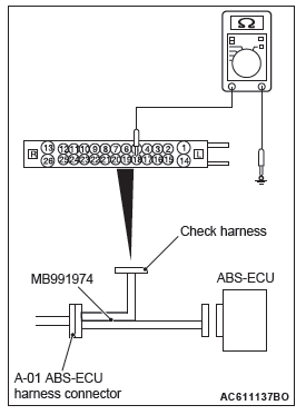
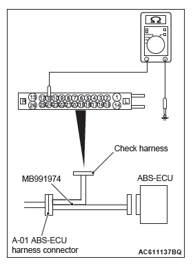
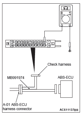
STEP 5. Resistance measurement at A-01 ABS-ECU connector
- Disconnect the ABS-ECU connector, connect special tool ABS check harness (MB991974) to the harness-side connector, and then measure the resistance at the special tool connector side.
NOTE: Do not connect the special tool ABS check harness (MB991974) to ABS-ECU.
- Measure the resistance between the front wheel speed sensor <LH> power supply terminal (signal terminal) No.18 and body ground, and between the ground terminal No.19 and body ground.
OK: No continuity
Q: Is the check result normal?
YES : Go to Step 8.
NO (Not normal at the terminal No.18 or 19) : Go to Step 6.
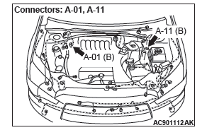
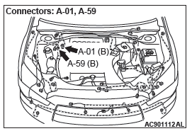
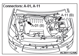
STEP 6. Connector check: A-01 ABS-ECU connector, A-11 front wheel speed sensor <LH> connector
Q: Is the check result normal?
YES : Go to Step 7.
NO : Repair the defective connector. Then go to Step 13.
STEP 7. Wiring harness check between A-01 ABS-ECU connector terminal No.18 and A-11 front wheel speed sensor <LH> connector terminal No.1, and between A-01 ABS-ECU connector terminal No.19 and A-11 front wheel speed sensor <LH> connector terminal No.2.
- Check for short circuit in front wheel speed sensor <LH> circuit
Q: Is the check result normal?
YES : Replace the wheel speed sensor <FL>. Then go to Step 13.
NO : Repair the wiring harness. Then go to Step 13.
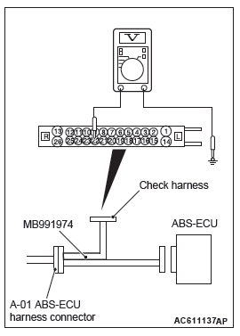
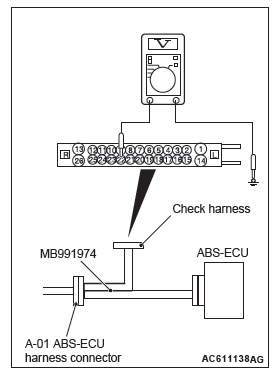
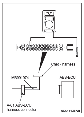
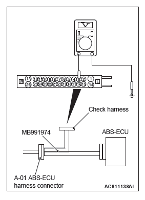
STEP 8. Voltage measurement at the A-01 ABS-ECU connector
- Disconnect the ABS-ECU connector, connect special tool ABS check harness (MB991974) to the ABS-ECU-side connector and harness-side connector, and then measure the voltage at the special tool connector side.
- Turn the ignition switch to the ON position.
- Measure the voltage between the front wheel speed sensor <LH> power supply terminal (signal terminal) No.18 and body ground, and between the ground terminal No.19 and body ground.
OK:
Terminal No.18 and body ground: Approximately
system voltage
Terminal No.19 and body ground: 1 volt or less
Q: Is the check result normal?
YES : Go to Step 9.
NO : Go to Step 11.
STEP 9. Wiring harness check between A-01 ABS-ECU connector terminal No.18 and A-11 front wheel speed sensor <LH> connector terminal No.1, and between A-01 ABS-ECU connector terminal No.19 and A-11 front wheel speed sensor <LH> connector terminal No.2.
- Check for open circuit in front wheel speed sensor <LH> circuit
Q: Is the check result normal?
YES : Go to Step 10.
NO : Repair the wiring harness. Then go to Step 13.
STEP 10. Check for wheel speed sensor <FL> as a single unit.
Q: Is the check result normal?
YES : Go to Step 11.
NO : Replace the wheel speed sensor <FL>. Then go to Step 13.
STEP 11. Connector check: A-01 ABS-ECU connector, A-11 front wheel speed sensor <LH> connector
Q: Is the check result normal?
YES : Go to Step 12.
NO : Repair the defective connector. Then go to Step 13.
STEP 12. Check whether the DTC is reset.
- Erase the DTC.
- Drive the vehicle at 12mph (20 km/h) or higher.
NOTE: The ABS warning light does not turn OFF in some cases unless the vehicle runs at 12mph (20 km/h) or higher.
Q: Is DTC C100A set?
YES : Replace the hydraulic unit (integrated with ABS-ECU). Then go to Step 13.
NO : Intermittent malfunction (Refer to GROUP 00 − How to Use Troubleshooting/How to Cope with Intermittent Malfunctions).
STEP 13. Check whether the DTC is reset.
- Erase the DTC.
- Drive the vehicle at 12mph (20 km/h) or higher.
NOTE: The ABS warning light does not turn OFF in some cases unless the vehicle runs at 12mph (20 km/h) or higher.
Q: Is DTC C100A set?
YES : Return to Step 1.
NO : The procedure is complete.
DTC C1015: Abnormality in FR wheel speed sensor circuit
Wheel Speed Sensor Circuit
CAUTION If there is any problem in the CAN bus lines, an incorrect DTC may be set. Prior to this diagnosis, diagnose the CAN bus lines (Refer to GROUP 54C − CAN Bus Line Diagnostic Flow).
CIRCUIT OPERATION
- The wheel speed sensor is a type of pulse generator. It consists of encoders (a plate on which north and south pole sides of the magnets are arranged alternately) for detecting the wheel speed which rotates at the same speed of the wheels and wheel speed sensors. This sensor outputs frequency pulse signals in proportion to the wheel speed.
- The pulse signals, which the wheel speed sensor creates, are sent to ABS-ECU. ABS-ECU uses the frequency of the pulse signals to determine the wheel speed.
DTC SET CONDITIONS
ABS-ECU monitors the voltage fluctuation in each wheel speed sensor circuit. If ABS-ECU detects the open or short circuit in the circuit, it will set a DTC.
PROBABLE CAUSES
Current trouble
- Damaged wiring harness and connectors
- Noise interference
- Malfunction of wheel speed sensor
- ABS-ECU malfunction
Past trouble
- Carry out diagnosis with particular emphasis on wiring harness and connector failures between ABS-ECU and the wheel speed sensor. For diagnosis procedures, refer to How to treat past trouble (GROUP 00 − How to Use Troubleshooting/ How to Treat Past Trouble).
DIAGNOSIS
Required Special Tools:
- MB991958: Scan Tool (M.U.T.-III Sub Assembly)
- MB991824: Vehicle Communication Interface (V.C.I.)
- MB991827: M.U.T.-III USB Cable
- MB991910: M.U.T.-III Main Harness A
- MB991974: ABS check harness
STEP 1. Using scan tool MB991958, diagnose the CAN bus line.
Use scan tool to diagnose the CAN bus lines.
Q: Is the check result normal?
YES : Go to Step 3.
NO : Repair the CAN bus lines (Refer to GROUP 54C − CAN Bus Diagnostics Table). On completion, go to Step 2.
STEP 2. DTC recheck after resetting CAN bus lines
Q: Is the DTC C1015 set?
YES : Go to Step 3.
NO : The procedure is complete.
STEP 3. Scan tool data list
Check the following data list.
- Item No.02: FR wheel speed sensor
Q: Is the check result normal?
YES : Go to Step 12.
NO : Go to Step 4.
STEP 4. Voltage measurement at the A-01 ABS-ECU connector
- Disconnect the ABS-ECU connector, connect special tool ABS check harness (MB991974) to the harness-side connector, and then measure the voltage at the special tool connector side.
NOTE: Do not connect the special tool ABS check harness (MB991974) to ABS-ECU.
- Turn the ignition switch to the ON position.
- Measure the voltage between the front wheel speed sensor <RH> power supply terminal (signal terminal) No.22 and body ground, and between the ground terminal No.21 and body ground.
OK: 1 volt or less
Q: Is the check result normal?
YES : Go to Step 5.
NO (Not normal at the terminal No.22 or 21) : Go to Step 6.
STEP 5. Resistance measurement at A-01 ABS-ECU connector
- Disconnect the ABS-ECU connector, connect special tool ABS check harness (MB991974) to the harness-side connector, and then measure the resistance at the special tool connector side.
NOTE: Do not connect the special tool ABS check harness (MB991974) to ABS-ECU.
- Measure the resistance between the front wheel speed sensor <RH> power supply terminal (signal terminal) No.22 and body ground, and between the wheel speed sensor ground terminal No.21 and body ground.
OK: No continuity
Q: Is the check result normal?
YES : Go to Step 8.
NO (Not normal at the terminal No.22 or 21) : Go to Step 6.
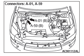
STEP 6. Connector check: A-01 ABS-ECU connector, A-59 front wheel speed sensor <RH> connector
Q: Is the check result normal?
YES : Go to Step 7.
NO : Repair the defective connector.
STEP 7. Wiring harness check between A-01 ABS-ECU connector terminal No.22 and A-59 front wheel speed sensor <RH> connector terminal No.1, and between A-01 ABS-ECU connector terminal No.21 and A-59 front wheel speed sensor <RH> connector terminal No.2.
- Check for short circuit in front wheel speed sensor <RH> circuit
Q: Is the check result normal?
YES : Replace the wheel speed sensor <FR>. Then go to Step 13.
NO : Repair the wiring harness. Then go to Step 13.
STEP 8. Voltage measurement at the A-01 ABS-ECU connector
- Disconnect the ABS-ECU connector, connect special tool ABS check harness (MB991974) to the ABS-ECU-side connector and harness-side connector, and then measure the voltage at the special tool connector side.
- Turn the ignition switch to the ON position.
- Measure the voltage between the front wheel speed sensor
<RH> power supply terminal (signal terminal) No.22 and
body ground, and between the ground terminal No.21 and
body ground.
OK:
Terminal No.22 and body ground: Approximately system voltage
Terminal No.21 and body ground: 1 volt or less
Q: Is the check result normal?
YES : Go to Step 9.
NO : Go to Step 11.
STEP 9. Wiring harness check between A-01 ABS-ECU connector terminal No.22 and A-59 front wheel speed sensor <RH> connector terminal No.1, and between A-01 ABS-ECU connector terminal No.21 and A-59 front wheel speed sensor <RH> connector terminal No.2.
- Check for open circuit in front wheel speed sensor <RH> circuit
Q: Is the check result normal?
YES : Go to Step 10.
NO : Repair the wiring harness. Then go to Step 13.
STEP 10. Check for wheel speed sensor <FR> as a single unit.
Q: Is the check result normal?
YES : Go to Step 11.
NO : Replace the wheel speed sensor <FR> . Then go to Step 13.
STEP 11. Connector check: A-01 ABS-ECU connector, A-59 front wheel speed sensor <RH> connector
Q: Is the check result normal?
YES : Go to Step 12.
NO : Repair the defective connector. Then go to Step 13.
STEP 12. Check whether the DTC is reset.
- Erase the DTC.
- Drive the vehicle at 12mph (20 km/h) or higher.
NOTE: The ABS warning light does not turn OFF in some cases unless the vehicle runs at 12mph (20 km/h) or higher.
Q: Is DTC C1015 set?
YES : Replace the hydraulic unit (integrated with ABS-ECU). Then go to Step 13.
NO : Intermittent malfunction (Refer to GROUP 00 − How to Use Troubleshooting/How to Cope with Intermittent Malfunctions).
STEP 13. Check whether the DTC is reset.
- Erase the DTC.
- Drive the vehicle at 12mph (20 km/h) or higher.
NOTE: The ABS warning light does not turn OFF in some cases unless the vehicle runs at 12mph (20 km/h) or higher.
Q: Is DTC C1015 set?
YES : Return to Step 1.
NO : The procedure is complete.
DTC C1020: Abnormality in RL wheel speed sensor circuit
Wheel Speed Sensor Circuit

CAUTION If there is any problem in the CAN bus lines, an incorrect DTC may be set. Prior to this diagnosis, diagnose the CAN bus lines (Refer to GROUP 54C − CAN Bus Line Diagnostic Flow).
CIRCUIT OPERATION
- The wheel speed sensor is a type of pulse generator. It consists of encoders (a plate on which north and south pole sides of the magnets are arranged alternately) for detecting the wheel speed which rotates at the same speed of the wheels and wheel speed sensors. This sensor outputs frequency pulse signals in proportion to the wheel speed.
- The pulse signals, which the wheel speed sensor creates, are sent to ABS-ECU. ABS-ECU uses the frequency of the pulse signals to determine the wheel speed.
DTC SET CONDITIONS
- ABS-ECU monitors the voltage fluctuation in each wheel speed sensor circuit. If ABS-ECU detects the open or short circuit in the circuit, it will set a DTC.
PROBABLE CAUSES
Current trouble
- Damaged wiring harness and connectors
- Noise interference
- Malfunction of wheel speed sensor
- ABS-ECU malfunction
Past trouble
- Carry out diagnosis with particular emphasis on wiring harness and connector failures between ABS-ECU and the wheel speed sensor. For diagnosis procedures, refer to How to treat past trouble.
DIAGNOSIS
Required Special Tools:
- MB991958: Scan Tool (M.U.T.-III Sub Assembly)
- MB991824: Vehicle Communication Interface (V.C.I.)
- MB991827: M.U.T.-III USB Cable
- MB991910: M.U.T.-III Main Harness A
- MB991974: ABS check harness
STEP 1. Using scan tool MB991958, diagnose the CAN bus line.
Use scan tool to diagnose the CAN bus lines.
Q: Is the check result normal?
YES : Go to Step 3.
NO : Repair the CAN bus lines (Refer to GROUP 54C − CAN Bus Diagnostics Table). On completion, go to Step 2.
STEP 2. DTC recheck after resetting CAN bus lines
Q: Is the DTC C1020 set?
YES : Go to Step 3.
NO : The procedure is complete.
STEP 3. Scan tool data list
Check the following data list.
- Item No.03: RL wheel speed sensor
Q: Is the check result normal?
YES : Go to Step 12.
NO : Go to Step 4.
STEP 4. Voltage measurement at the A-01 ABS-ECU connector
- Disconnect the ABS-ECU connector, connect special tool
ABS check harness (MB991974) to the harness-side
connector, and then measure the voltage at the special tool
connector side.
NOTE: Do not connect the special tool ABS check harness (MB991974) to ABS-ECU.
- Turn the ignition switch to the ON position.
- Measure the voltage between the rear wheel speed sensor
<LH> power supply terminal (signal terminal) No.24 and
body ground, and between the wheel speed sensor ground
terminal No.25 and body ground.
OK: 1 volt or less
Q: Is the check result normal?
YES : Go to Step 5.
NO (Not normal at the terminal No.24 or No.25) : Go to Step 6.
STEP 5. Resistance measurement at A-01 ABS-ECU connector
- Disconnect the ABS-ECU connector, connect special tool
ABS check harness (MB991974) to the harness-side
connector, and then measure the resistance at the special
tool connector side.
NOTE: Do not connect the special tool ABS check harness (MB991974) to ABS-ECU.
- Measure the resistance between the rear wheel speed
sensor <LH> power supply terminal (signal terminal) No.24
and body ground, and between the ground terminal No.25
and body ground.
OK: No continuity
Q: Is the check result normal?
YES : Go to Step 8.
NO (Not normal at the terminal No.24 or No.25) : Go to Step 6.
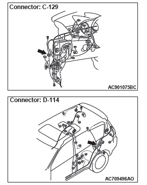
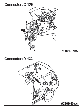
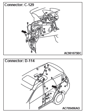
STEP 6. Connector check: A-01 ABS-ECU connector, C-129 intermediate connector, D-114 rear wheel speed sensor <LH> connector
Q: Is the check result normal?
YES : Go to Step 7.
NO : Repair the defective connector. Then go to Step 13.
STEP 7. Wiring harness check between A-01 ABS-ECU connector terminal No.24 and D-114 rear wheel speed sensor <LH> connector terminal No.1, and between A-01 ABS-ECU connector terminal No.25 and D-114 rear wheel speed sensor <LH> connector terminal No.2.
- Check for short circuit in rear wheel speed sensor <LH> circuit
Q: Is the check result normal?
YES : Replace the wheel speed sensor <RL> . Then go to Step 13.
NO : Repair the wiring harness. Then go to Step 13.
STEP 8. Voltage measurement at the A-01 ABS-ECU connector
- Disconnect the ABS-ECU connector, connect special tool ABS check harness (MB991974) to the ABS-ECU-side connector and harness-side connector, and then measure the voltage at the special tool connector side.
- Turn the ignition switch to the ON position.
- Measure the voltage between the rear wheel speed sensor
<LH> power supply terminal (signal terminal) No.24 and
body ground, and between the ground terminal No.25 and
body ground.
OK:
Terminal No.24 and body ground: Approximately system voltage
Terminal No.25 and body ground: 1 volt or less
Q: Is the check result normal?
YES : Go to Step 9.
NO : Go to Step 11.
STEP 9. Wiring harness check between A-01 ABS-ECU connector terminal No.24 and D-114 rear wheel speed sensor <LH> connector terminal No.1, and between A-01 ABS-ECU connector terminal No.25 and D-114 rear wheel speed sensor <LH> connector terminal No.2.
- Check for open circuit in rear wheel speed sensor <LH> circuit
Q: Is the check result normal?
YES : Go to Step 10.
NO : Repair the wiring harness.
STEP 10. Check for wheel speed sensor <RL> as a single unit. Q: Is the check result normal?
YES : Go to Step 11.
NO : Replace the wheel speed sensor <RL> . Then go to Step 13.
STEP 11. Connector check: A-01 ABS-ECU connector, C-129 intermediate connector, D-114 rear wheel speed sensor <LH> connector
Q: Is the check result normal?
YES : Go to Step 12.
NO : Repair the defective connector. Then go to Step 13.
STEP 12. Check whether the DTC is reset.
- Erase the DTC.
- Drive the vehicle at 12mph (20 km/h) or higher.
NOTE: The ABS warning light does not turn OFF in some cases unless the vehicle runs at 12mph (20 km/h) or higher.
Q: Is DTC C1020 set?
YES : Replace the hydraulic unit (integrated with ABS-ECU). Then go to Step 13.
NO : Intermittent malfunction (Refer to GROUP 00 − How to Use Troubleshooting/How to Cope with Intermittent Malfunctions).
STEP 13. Check whether the DTC is reset.
- Erase the DTC.
- Drive the vehicle at 12mph (20 km/h) or higher.
NOTE: The ABS warning light does not turn OFF in some cases unless the vehicle runs at 12mph (20 km/h) or higher.
Q: Is DTC C1020 set?
YES : Return to Step 1.
NO : The procedure is complete.
DTC C102B: Abnormality in RR wheel speed sensor circuit
Wheel Speed Sensor Circuit

CAUTION If there is any problem in the CAN bus lines, an incorrect DTC may be set. Prior to this diagnosis, diagnose the CAN bus lines (Refer to GROUP 54C − CAN Bus Line Diagnostic Flow).
CIRCUIT OPERATION
- The wheel speed sensor is a type of pulse generator. It consists of encoders (a plate on which north and south pole sides of the magnets are arranged alternately) for detecting the wheel speed which rotates at the same speed of the wheels and wheel speed sensors. This sensor outputs frequency pulse signals in proportion to the wheel speed.
- The pulse signals, which the wheel speed sensor creates, are sent to ABS-ECU. ABS-ECU uses the frequency of the pulse signals to determine the wheel speed.
DTC SET CONDITIONS
ABS-ECU monitors the voltage fluctuation in each wheel speed sensor circuit. If ABS-ECU detects the open or short circuit in the circuit, it will set a DTC.
PROBABLE CAUSES
Current trouble
- Damaged wiring harness and connectors
- Noise interference
- Malfunction of wheel speed sensor
- ABS-ECU malfunction
Past trouble
- Carry out diagnosis with particular emphasis on wiring harness and connector failures between ABS-ECU and the wheel speed sensor. For diagnosis procedures, refer to How to treat past trouble (Refer to GROUP 00 − How to Use Troubleshooting/How to Treat Past Trouble).
DIAGNOSIS
Required Special Tools:
- MB991958: Scan Tool (M.U.T.-III Sub Assembly)
- MB991824: Vehicle Communication Interface (V.C.I.)
- MB991827: M.U.T.-III USB Cable
- MB991910: M.U.T.-III Main Harness A
- MB991974: ABS check harness
STEP 1. Using scan tool MB991958, diagnose the CAN bus line.
Use scan tool to diagnose the CAN bus lines.
Q: Is the check result normal?
YES : Go to Step 3.
NO : Repair the CAN bus lines (Refer to GROUP 54C − CAN Bus Diagnostics Table). On completion, go to Step 2.
STEP 2. DTC recheck after resetting CAN bus lines
Q: Is the DTC C102B set?
YES : Go to Step 3.
NO : The procedure is complete.
STEP 3. Scan tool data list
Check the following data list.
- Item No.04: RR wheel speed sensor
Q: Is the check result normal?
YES : Go to Step 12.
NO : Go to Step 4.
STEP 4. Voltage measurement at the A-01 ABS-ECU connector
- Disconnect the ABS-ECU connector, connect special tool
ABS check harness (MB991974) to the harness-side
connector, and then measure the voltage at the special tool
connector side.
NOTE: Do not connect the special tool ABS check harness (MB991974) to ABS-ECU.
- Turn the ignition switch to the ON position.
- Measure the voltage between the rear wheel speed sensor
<RH> power supply terminal (signal terminal) No.16 and
body ground, and between the wheel speed sensor ground
terminal No.15 and body ground.
OK: 1 volt or less
Q: Is the check result normal?
YES : Go to Step 5.
NO (Not normal at the terminal No.16 or 15) : Go to Step 6.
STEP 5. Resistance measurement at A-01 ABS-ECU connector
- Disconnect the ABS-ECU connector, connect special tool
ABS check harness (MB991974) to the harness-side
connector, and then measure the resistance at the special
tool connector side.
NOTE: Do not connect the special tool ABS check harness (MB991974) to ABS-ECU.
- Measure the resistance between the rear wheel speed
sensor <RH> power supply terminal (signal terminal) No.16
and body ground, and between the ground terminal No.15
and body ground.
OK: No continuity
Q: Is the check result normal?
YES : Go to Step 8.
NO (Not normal at the terminal No.16 or 15) : Go to Step 6.
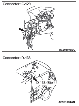
STEP 6. Connector check: A-01 ABS-ECU connector, C-129 intermediate connector, D-133 rear wheel speed sensor <RH> connector
Q: Is the check result normal?
YES : Go to Step 7.
NO : Repair the defective connector. Then go to Step 13.
STEP 7. Wiring harness check between A-01 ABS-ECU connector terminal No.16 and D-133 rear wheel speed sensor <RH> connector terminal No.1, and between A-01 ABS-ECU connector terminal No.15 and D-133 rear wheel speed sensor <RH> connector terminal No.2.
- Check for short circuit in rear wheel speed sensor <RH> circuit
Q: Is the check result normal?
YES : Replace the wheel speed sensor <RR>. Then go to Step 13.
NO : Repair the wiring harness. Then go to Step 13.
STEP 8. Voltage measurement at the A-01 ABS-ECU connector
- Disconnect the ABS-ECU connector, connect special tool ABS check harness (MB991974) to the ABS-ECU-side connector and harness-side connector, and then measure the voltage at the special tool connector side.
- Turn the ignition switch to the ON position.
- Measure the voltage between the rear wheel speed sensor
<RH> power supply terminal (signal terminal) No.16 and
body ground, and between the ground terminal No.15 and
body ground.
OK:
Terminal No.16 and body ground: Approximately system voltage
Terminal No.15 and body ground: 1 volt or less
Q: Is the check result normal?
YES : Go to Step 9.
NO : Go to Step 11.
STEP 9. Wiring harness check between A-01 ABS-ECU connector terminal No.16 and D-133 rear wheel speed sensor <RH> connector terminal No.1, and between A-01 ABS-ECU connector terminal No.15 and D-133 rear wheel speed sensor <RH> connector terminal No.2.
- Check for open circuit in rear wheel speed sensor <RH> circuit
Q: Is the check result normal?
YES : Go to Step 10.
NO : Repair the wiring harness.
STEP 10. Check for wheel speed sensor <RR> as a single unit
Q: Is the check result normal?
YES : Go to Step 11.
NO : Replace the wheel speed sensor <RR>. Then go to Step 13.
STEP 11. Connector check: A-01 ABS-ECU connector, C-129 intermediate connector, D-133 rear wheel speed sensor <RH> connector
Q: Is the check result normal?
YES : Go to Step 12.
NO : Repair the defective connector. Then go to Step 13.
STEP 12. Check whether the DTC is reset.
- Erase the DTC.
- Drive the vehicle at 12mph (20 km/h) or higher.
NOTE: The ABS warning light does not turn OFF in some cases unless the vehicle runs at 12mph (20 km/h) or higher.
Q: Is DTC C102B set?
YES : Replace the hydraulic unit (integrated with ABS-ECU). Then go to Step 13.
NO : Intermittent malfunction (Refer to GROUP 00 − How to Use Troubleshooting/How to Cope with Intermittent Malfunctions).
STEP 13. Check whether the DTC is reset.
- Erase the DTC.
- Drive the vehicle at 12mph (20 km/h) or higher.
NOTE: The ABS warning light does not turn OFF in some cases unless the vehicle runs at 12mph (20 km/h) or higher.
Q: Is DTC C102B set?
YES : Return to Step 1.
NO : The procedure is complete.
DTC C1011: Abnormality in FL wheel speed sensor signal
Wheel Speed Sensor Circuit
CAUTION If there is any problem in the CAN bus lines, an incorrect DTC may be set. Prior to this diagnosis, diagnose the CAN bus lines (Refer to GROUP 54C − CAN Bus Line Diagnostic Flow).
CIRCUIT OPERATION
- The wheel speed sensor is a type of pulse generator. It consists of encoders (a plate on which north and south pole sides of the magnets are arranged alternately) for detecting the wheel speed which rotates at the same speed of the wheels and wheel speed sensors. This sensor outputs frequency pulse signals in proportion to the wheel speed.
- The pulse signals, which the wheel speed sensor creates, are sent to ABS-ECU. ABS-ECU uses the frequency of the pulse signals to determine the wheel speed.
DTC SET CONDITIONS
ABS-ECU monitors the signals from each wheel speed sensor while the vehicle is being driven. If any fault below is found in these sensor signals, ABS-ECU will set the relevant DTC.
- Irregular change in the wheel speed sensor signal
- Wheel speed sensor signal continuously indicates high value.
PROBABLE CAUSES
Current trouble
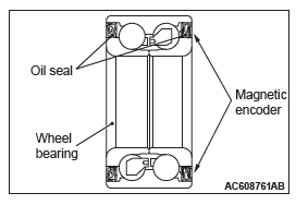
- Excessive gap between the wheel speed sensor and the magnetic encoder for wheel speed detection
- Adhesion of foreign materials on the wheel speed sensor
- Adhesion of foreign materials on the wheel speed detection encoder
- Wheel bearing malfunction
- Malfunction of wheel speed sensor
- Damaged wiring harness and connectors
- External noise interference
- Improper installation of the wheel speed sensor
- Deformation of the wheel speed detection encoder
- ABS-ECU malfunction
- Disturbance of magnetization pattern for magnetic encoder for wheel speed detection
- The number of poles on the magnetic encoder for wheel speed detection (the number of N-pole and S-pole) is changed.
Past trouble
- When the DTC No.C100A is also set, carry out diagnosis
with particular emphasis on wiring harness and connector
failures between ABS-ECU and the wheel speed sensor.
For diagnosis procedures, refer to How to treat past trouble (Refer to GROUP 00 − How to Use Troubleshooting/How to Treat Past Trouble).
- When the DTC No.C100A is not set, the following conditions
may be present:
- Some wheels slip
- Unstable vehicle attitude
- External noise interference
- Vehicle ran with the parking brake applied.
DIAGNOSIS
Required Special Tools:
- MB991958: Scan Tool (M.U.T.-III Sub Assembly)
- MB991824: Vehicle Communication Interface (V.C.I.)
- MB991827: M.U.T.-III USB Cable
- MB991910: M.U.T.-III Main Harness A
STEP 1. Using scan tool MB991958, diagnose the CAN bus lines.
Use scan tool to diagnose the CAN bus lines.
Q: Is the check result normal?
YES : Go to Step 3.
NO : Repair the CAN bus lines (Refer to GROUP 54C − CAN Bus Diagnostics Table). On completion, go to Step 2.
STEP 2. DTC recheck after resetting CAN bus lines
Q: Is DTC C1011 set?
YES : Go to Step 3.
NO : The procedure is complete.
STEP 3. Using scan tool MB991958, check the DTC
Check that the DTC C100A is also set.
Q: Is DTC C100A also set?
YES : Perform the diagnosis for the DTC C100A.
NO : Go to Step 4.
STEP 4. Connector check: A-01 ABS-ECU connector, A-11 front wheel speed sensor <LH> connector
Q: Is the check result normal?
YES : Go to Step 5.
NO : Repair the defective connector. Then go to Step 12.
STEP 5. Wiring harness check between A-01 ABS-ECU connector terminal No.18 and A-11 front wheel speed sensor <LH> connector terminal No.1, and between A-01 ABS-ECU connector terminal No.19 and A-11 front wheel speed sensor <LH> connector terminal No.2.
Q: Is the check result normal?
YES : Go to Step 6.
NO : Repair the wiring harness. Then go to Step 12.
STEP 6. Check wheel speed sensor <FL> installation
Check how the wheel speed sensor <FL> is installed (Disconnection of wheel speed sensor <FL>, loose mounting bolt, etc.).
Q: Is the check result normal?
YES : Go to Step 7.
NO : Reinstall the wheel speed sensor <FL>. Then go to Step 7.
STEP 7. Check for wheel speed sensor <FL> output current.
Q: Is the check result normal?
YES : Go to Step 8.
NO : Replace the wheel speed sensor <FL>. Then go to Step 11.
STEP 8. Check for wheel bearing looseness
NOTE:
- Loose wheel bearing may increase the gap between the wheel speed sensor <FL> and the wheel speed detection magnet encoder.
- Check the wheel bearing <FL> for looseness (Refer to GROUP 26 − Wheel Bearing Play Check).
Q: Is the check result normal?
YES : Go to Step 9.
NO : Replace the wheel bearing <FL> (Refer to GROUP 26 − Front Axle Hub Assembly). Then go to Step 12.
STEP 9. Check wheel speed detection encoder
Check the encoder for adhesion of foreign materials or deformation.
Q: Is the check result normal?
YES : Go to Step 10.
NO (Adhesion of foreign materials) : Remove the foreign materials and clean the encoder so as not to disturb the magnetization pattern on it while taking care of the magnet, magnetic substance, and magnetic attraction. Then go to Step 12.
NO (Deformation) : Replace the wheel bearing <FL> (Refer to GROUP 26 − Front Axle Hub Assembly). Then go to Step 12.
STEP 10. Check whether the DTC is reset.
- Erase the DTC.
- Drive the vehicle at 12mph (20 km/h) or higher.
NOTE: The ABS warning light does not turn OFF in some cases unless the vehicle runs at 12mph (20 km/h) or higher.
Q: Is DTC C1011 set?
YES : Replace the wheel speed sensor <FL>. Then go to Step 11.
NO : Intermittent malfunction (Refer to GROUP 00 − How to Use Troubleshooting/How to Cope with Intermittent Malfunctions).
STEP 11. Check whether the DTC is reset.
- Erase the DTC.
- Drive the vehicle at 12mph (20 km/h) or higher.
NOTE: The ABS warning light does not turn OFF in some cases unless the vehicle runs at 12mph (20 km/h) or higher.
Q: Is DTC C1011 set?
YES : Replace the hydraulic unit (integrated with ABS-ECU). Then go to Step 12.
NO : The procedure is complete.
STEP 12. Check whether the DTC is reset.
- Erase the DTC.
- Drive the vehicle at 12mph (20 km/h) or higher.
NOTE: The ABS warning light does not turn OFF in some cases unless the vehicle runs at 12mph (20 km/h) or higher.
Q: Is DTC C1011 set?
YES : Return to Step 1.
NO : The procedure is complete.
DTC C101C Abnormality in FR wheel speed sensor signal
Wheel Speed Sensor Circuit
CAUTION If there is any problem in the CAN bus lines, an incorrect DTC may be set. Prior to this diagnosis, diagnose the CAN bus lines (Refer to GROUP 54C − CAN Bus Line Diagnostic Flow).
CIRCUIT OPERATION
- The wheel speed sensor is a type of pulse generator. It consists of encoders (a plate on which north and south pole sides of the magnets are arranged alternately) for detecting the wheel speed which rotates at the same speed of the wheels and wheel speed sensors. This sensor outputs frequency pulse signals in proportion to the wheel speed.
- The pulse signals, which the wheel speed sensor creates, are sent to ABS-ECU. ABS-ECU uses the frequency of the pulse signals to determine the wheel speed.
DTC SET CONDITIONS
ABS-ECU monitors the signals from each wheel speed sensor while the vehicle is being driven. If any fault below is found in these sensor signals, ABS-ECU will set the relevant DTC.
- Irregular change in the wheel speed sensor signal
- Wheel speed sensor signal continuously indicates high value.
PROBABLE CAUSES
Current trouble
- Excessive gap between the wheel speed sensor and the magnetic encoder for wheel speed detection
- Adhesion of foreign materials on the wheel speed sensor
- Adhesion of foreign materials on the wheel speed detection encoder
- Wheel bearing malfunction
- Malfunction of wheel speed sensor
- Damaged wiring harness and connectors
- External noise interference
- Improper installation of the wheel speed sensor
- Deformation of the wheel speed detection encoder
- ABS-ECU malfunction
- Disturbance of magnetization pattern for wheel speed detection encoder
- The number of poles on the magnetic encoder for wheel speed detection (the number of N-pole and S-pole) is changed.
Past trouble
- When the DTC C1015 is also set, carry out diagnosis with particular emphasis on wiring harness and connector failures between ABS-ECU and the wheel speed sensor. For diagnosis procedures, refer to How to treat past trouble (Refer to GROUP 00 − How to Use Troubleshooting/How to Treat Past Trouble).
- When DTC C1015 is not set, the following conditions may
be present:
- Some wheels slip
- Unstable vehicle attitude
- External noise interference
- Vehicle ran with the parking brake applied.
DIAGNOSIS
Required Special Tools:
- MB991958: Scan Tool (M.U.T.-III Sub Assembly)
- MB991824: Vehicle Communication Interface (V.C.I.)
- MB991827: M.U.T.-III USB Cable
- MB991910: M.U.T.-III Main Harness A
STEP 1. Using scan tool MB991958, diagnose the CAN bus lines.
Use scan tool to diagnose the CAN bus lines.
Q: Is the check result normal?
YES : Go to Step 3.
NO : Repair the CAN bus lines (Refer to GROUP 54C − CAN Bus Diagnostics Table). On completion, go to Step 2.
STEP 2. DTC recheck after resetting CAN bus lines
Q: Is DTC C101C set?
YES : Go to Step 3.
NO : The procedure is complete.
STEP 3. Using scan tool MB991958, check the DTC
Check that the DTC C1015 is also set.
Q: Is DTC C1015 also set?
YES : Perform the diagnosis for the DTC C1015.
NO : Go to Step 4.
STEP 4. Connector check: A-01 ABS-ECU connector, A-59 front wheel speed sensor <RH> connector
Q: Is the check result normal?
YES : Go to Step 5.
NO : Repair the defective connector. Then go to Step 12.
STEP 5. Wiring harness check between A-01 ABS-ECU connector terminal No.22 and A-59 front wheel speed sensor <RH> connector terminal No.1, and between A-01 ABS-ECU connector terminal No.21 and A-59 front wheel speed sensor <RH> connector terminal No.2.
Q: Is the check result normal?
YES : Go to Step 6.
NO : Repair the wiring harness. Then go to Step 12.
STEP 6. Check wheel speed sensor <FR> installation Check how the wheel speed sensor <FR> is installed (Disconnection of wheel speed sensor <FR>, loose mounting bolt, etc.).
Q: Is the check result normal?
YES : Go to Step 7.
NO : Reinstall the wheel speed sensor <FR> correctly. Then go to Step 7.
STEP 7. Check for wheel speed sensor <FR> output current
Q: Is the check result normal?
YES : Go to Step 8.
NO : Replace the wheel speed sensor <FR>. Then go to Step 11.
STEP 8. Check for wheel bearing looseness
NOTE:
- Loose wheel bearing may increase the gap between the wheel speed sensor <FR> and the wheel speed detection magnet encoder.
- Check the wheel bearing <FR> for looseness (Refer to GROUP 26 − Wheel Bearing Play Check).
Q: Is the check result normal?
YES : Go to Step 9.
NO : Replace the wheel bearing <FR> (Refer to GROUP 26 − Front Axle Hub Assembly). Then go to Step 12.
STEP 9. Check wheel speed detection encoder
Check the encoder for adhesion of foreign materials or deformation.
Q: Is the check result normal?
YES : Go to Step 10.
NO (Adhesion of foreign materials) : Remove the foreign materials and clean the encoder so as not to disturb the magnetization pattern on it while taking care of the magnet, magnetic substance, and magnetic attraction. Then go to Step 12.
NO (Deformation) : Replace the wheel bearing <FR> (Refer to GROUP 26 − Front Axle Hub Assembly). Then go to Step 12.
STEP 10. Check whether the DTC is reset.
- Erase the DTC.
- Drive the vehicle at 12mph (20 km/h) or higher.
NOTE: The ABS warning light does not turn OFF in some cases unless the vehicle runs at 12mph (20 km/h) or higher.
Q: Is DTC C101C set?
YES : Replace the wheel speed sensor <FR>. Then go to Step 11.
NO : Intermittent malfunction (Refer to GROUP 00 − How to Use Troubleshooting/How to Cope with Intermittent Malfunctions).
STEP 11. Check whether the DTC is reset.
- Erase the DTC.
- Drive the vehicle at 12mph (20 km/h) or higher.
NOTE: The ABS warning light does not turn OFF in some cases unless the vehicle runs at 12mph (20 km/h) or higher.
Q: Is DTC C101C set?
YES : Replace the hydraulic unit (integrated with ABS-ECU). Then go to Step 12.
NO : The procedure is complete.
STEP 12. Check whether the DTC is reset.
- Erase the DTC.
- Drive the vehicle at 12mph (20 km/h) or higher.
NOTE: The ABS warning light does not turn OFF in some cases unless the vehicle runs at 12mph (20 km/h) or higher.
Q: Is DTC C101C set?
YES : Return to Step 1.
NO : The procedure is complete.
DTC C1027: Abnormality in RL wheel speed sensor signal
Wheel Speed Sensor Circuit
CAUTION If there is any problem in the CAN bus lines, an incorrect DTC may be set. Prior to this diagnosis, diagnose the CAN bus lines (Refer to GROUP 54C − CAN Bus Line Diagnostic Flow).
CIRCUIT OPERATION
- The wheel speed sensor is a type of pulse generator. It consists of encoders (a plate on which north and south pole sides of the magnets are arranged alternately) for detecting the wheel speed which rotates at the same speed of the wheels and wheel speed sensors. This sensor outputs frequency pulse signals in proportion to the wheel speed.
- The pulse signals, which the wheel speed sensor creates, are sent to ABS-ECU. ABS-ECU uses the frequency of the pulse signals to determine the wheel speed.
DTC SET CONDITIONS
ABS-ECU monitors the signals from each wheel speed sensor while the vehicle is being driven. If any fault below is found in these sensor signals, ABS-ECU will set the relevant DTC.
- Irregular change in the wheel speed sensor signal
- Wheel speed sensor signal continuously indicates higher value than the values of other wheel speed sensors.
PROBABLE CAUSES
Current trouble
- Excessive gap between the wheel speed sensor and the magnetic encoder for wheel speed detection
- Adhesion of foreign materials on the wheel speed sensor
- Adhesion of foreign materials on the magnetic encoder for wheel speed detection
- Wheel bearing malfunction
- Malfunction of wheel speed sensor
- Damaged wiring harness and connectors
- External noise interference
- Improper installation of the wheel speed sensor
- Deformation of the magnetic encoder for wheel speed detection
- ABS-ECU malfunction
- Disturbance of magnetization pattern for magnetic encoder for wheel speed detection
- The number of poles on the magnetic encoder for wheel speed detection (the number of N-pole and S-pole) is changed.
Past trouble
- When the DTC C1020 is also set, carry out diagnosis with particular emphasis on wiring harness and connector failures between ABS-ECU and the wheel speed sensor. For diagnosis procedures, refer to How to treat past trouble (Refer to GROUP 00 − How to Use Troubleshooting/How to Treat Past Trouble).
- When the DTC C1020 is not set, the following conditions
may be present:
- Right or/and left wheels are rotated.
- Unstable vehicle attitude
- External noise interference
- Vehicle ran with the parking brake applied.
DIAGNOSIS
Required Special Tools:
- MB991958: Scan Tool (M.U.T.-III Sub Assembly)
- MB991824: Vehicle Communication Interface (V.C.I.)
- MB991827: M.U.T.-III USB Cable
- MB991910: M.U.T.-III Main Harness A
STEP 1. Using scan tool MB991958, diagnose the CAN bus lines.
Use scan tool to diagnose the CAN bus lines.
Q: Is the check result normal?
YES : Go to Step 3.
NO : Repair the CAN bus lines (Refer to GROUP 54C − CAN Bus Diagnostics Table). On completion, go to Step 2.
STEP 2. DTC recheck after resetting CAN bus lines
Q: Is DTC C1027 set?
YES : Go to Step 3.
NO : The procedure is complete.
STEP 3. Using scan tool MB991958, check the DTC
Check that the DTC C1020 is also set.
Q: Is DTC C1020 also set?
YES : Perform the diagnosis for the DTC C1020.
NO : Go to Step 4.
STEP 4. Connector check: A-01 ABS-ECU connector, C-129 intermediate connector, D-114 rear wheel speed sensor <LH> connector
Q: Is the check result normal?
YES : Go to Step 5.
NO : Repair the defective connector. Then go to Step 12.
STEP 5. Wiring harness check between A-01 ABS-ECU connector terminal No.24 and D-114 rear wheel speed sensor <LH> connector terminal No.1, and between A-01 ABS-ECU connector terminal No.25 and D-114 rear wheel speed sensor <LH> connector terminal No.2.
Q: Is the check result normal?
YES : Go to Step 6.
NO : Repair the wiring harness. Then go to Step 12.
STEP 6. Check wheel speed sensor <RL> installation
Check how the wheel speed sensor <RL> is installed (Disconnection of wheel speed sensor <RL>, loose mounting bolt, etc.).
Q: Is the check result normal?
YES : Go to Step 7.
NO : Reinstall the wheel speed sensor <RL> correctly. Then go to Step 7.
STEP 7. Check for wheel speed sensor <RL> output current
Q: Is the check result normal?
YES : Go to Step 8.
NO : Replace the wheel speed sensor <RL>. Then go to Step 11.
STEP 8. Check for wheel bearing looseness
NOTE:
- Loose wheel bearing may increase the gap between the wheel speed sensor <RL>and the wheel speed detection magnet encoder.
- Check the wheel bearing <RL> for looseness (Refer to GROUP 27A − On-vehicle Service).
Q: Is the check result normal?
YES : Go to Step 9.
NO : Replace the rear wheel hub assembly <RL> (Refer to GROUP 27A − Rear Axle Hub Assembly).
Then go to Step 12.
STEP 9. Check wheel speed detection encoder
Check the encoder for adhesion of foreign materials or deformation.
Q: Is the check result normal?
YES : Go to Step 10.
NO (Adhesion of foreign materials) : Remove the foreign materials and clean the encoder so as not to disturb the magnetization pattern on it while taking care of the magnet, magnetic substance, and magnetic attraction. Then go to Step 12.
NO (Deformation) : Replace the rear wheel hub assembly <RL> (Refer to GROUP 27A − Rear Axle Hub Assembly). Then go to Step 12.
STEP 10. Check whether the DTC is reset.
- Erase the DTC.
- Drive the vehicle at 12mph (20 km/h) or higher.
NOTE: The ABS warning light does not turn OFF in some cases unless the vehicle runs at 12mph (20 km/h) or higher.
Q: Is DTC C1027 set?
YES : Replace the wheel speed sensor <RL>. Then go to Step 11.
NO : Intermittent malfunction (Refer to GROUP 00 − How to Use Troubleshooting/How to Cope with Intermittent Malfunctions).
STEP 11. Check whether the DTC is reset.
- Erase the DTC.
- Drive the vehicle at 12mph (20 km/h) or higher.
NOTE: The ABS warning light does not turn OFF in some cases unless the vehicle runs at 12mph (20 km/h) or higher.
Q: Is DTC C1027 set?
YES : Replace the hydraulic unit (integrated with ABS-ECU). Then go to Step 12.
NO : The procedure is complete.
STEP 12. Check whether the DTC is reset.
- Erase the DTC.
- Drive the vehicle at 12mph (20 km/h) or higher.
NOTE: The ABS warning light does not turn OFF in some cases unless the vehicle runs at 12mph (20 km/h) or higher.
Q: Is DTC C1027 set?
YES : Return to Step 1.
NO : The procedure is complete.
DTC C1032: Abnormality in RR wheel speed sensor signal
Wheel Speed Sensor Circuit

CAUTION If there is any problem in the CAN bus lines, an incorrect DTC may be set. Prior to this diagnosis, diagnose the CAN bus lines (Refer to GROUP 54C − CAN Bus Line Diagnostic Flow).
CIRCUIT OPERATION
- The wheel speed sensor is a type of pulse generator. It consists of encoders (a plate on which north and south pole sides of the magnets are arranged alternately) for detecting the wheel speed which rotates at the same speed of the wheels and wheel speed sensors. This sensor outputs frequency pulse signals in proportion to the wheel speed.
- The pulse signals, which the wheel speed sensor creates, are sent to ABS-ECU. ABS-ECU uses the frequency of the pulse signals to determine the wheel speed.
DTC SET CONDITIONS
ABS-ECU monitors the signals from each wheel speed sensor while the vehicle is being driven. If any fault below is found in these sensor signals, ABS-ECU will set the relevant DTC.
- Irregular change in the wheel speed sensor signal
- Wheel speed sensor signal continuously indicates higher value than the values of other wheel speed sensors.
PROBABLE CAUSES
Current trouble
- Excessive gap between the wheel speed sensor and the magnetic encoder for wheel speed detection
- Adhesion of foreign materials on the wheel speed sensor
- Adhesion of foreign materials on the magnetic encoder for wheel speed detection
- Wheel bearing malfunction
- Malfunction of wheel speed sensor
- Damaged wiring harness and connectors
- External noise interference
- Improper installation of the wheel speed sensor
- Deformation of the magnetic encoder for wheel speed detection
- ABS-ECU malfunction
- Disturbance of magnetization pattern for magnetic encoder for wheel speed detection
- The number of poles on the magnetic encoder for wheel speed detection (the number of N-pole and S-pole) is changed.
Past trouble
- When the DTC C102B is also set, carry out diagnosis with particular emphasis on wiring harness and connector failures between ABS-ECU and the wheel speed sensor. For diagnosis procedures, refer to How to treat past trouble (Refer to GROUP 00 − How to Use Troubleshooting/How to Treat Past Trouble).
- When the DTC C102B is not set, the following conditions
may be present:
- Right or/and left wheels are rotated.
- Unstable vehicle attitude
- External noise interference
- Vehicle ran with the parking brake applied.
DIAGNOSIS
Required Special Tools:
- MB991958: Scan Tool (M.U.T.-III Sub Assembly)
- MB991824: Vehicle Communication Interface (V.C.I.)
- MB991827: M.U.T.-III USB Cable
- MB991910: M.U.T.-III Main Harness A
STEP 1. Using scan tool MB991958, diagnose the CAN bus lines.
Use scan tool to diagnose the CAN bus lines.
Q: Is the check result normal?
YES : Go to Step 3.
NO : Repair the CAN bus lines (Refer to GROUP 54C − CAN Bus Diagnostics Table). On completion, go to Step 2.
STEP 2. DTC recheck after resetting CAN bus lines
Q: Is DTC C1032 set?
YES : Go to Step 3.
NO : The procedure is complete.
STEP 3. Using scan tool MB991958, check the DTC
Check that the DTC C102B is also set.
Q: Is DTC C102B also set?
YES : Perform the diagnosis for the DTC C102B.
NO : Go to Step 4.
STEP 4. Connector check: A-01 ABS-ECU connector,
C-129 intermediate connector, READ NEXT:
DTC C1041: Abnormality in periodical signal for FL wheel speed sensor
CAUTION
If there is any problem in the CAN bus lines, an incorrect
DTC may be set. Prior to this diagnosis, diagnose
the CAN b
 DTC C1041, C1042, C1043, C1044, C1046, C1047, C1048, C1049, C104B,
C104F, C1053, C1057, C105F, C1063, C1067, C105B
DTC C1041, C1042, C1043, C1044, C1046, C1047, C1048, C1049, C104B,
C104F, C1053, C1057, C105F, C1063, C1067, C105B
DTC C2104 Faulty valve power supply circuit
Power Supply Circuit
CAUTION
If there is any problem in the CAN bus lines, an incorrect
DTC may be set. Prior to this diagnosis, diagnose the CAN
bus line
DTC C2104, C1073, C2116, C1000, C2200, C2100, C2101, C1395, C2203,
C1608, U0001, U0100, U0141, U1415, U1417
SYMPTOM CHART
CAUTION
ABS may operate in the following conditions without hard braking:
Slippery road surface,
high-speed turn, and bumpy road surface. When asking the customers, confirm
that t
Symptom Chart, Symptom Procedures
SEE MORE:
DIAGNOSTIC ITEM 6: Diagnose when the scan tool cannot receive the data
sent by AWD-ECU
<Electronic controlled AWD>.
CAUTION
When servicing a CAN bus line, ground yourself by touching a metal object such
as an unpainted
water pipe. If you fail to do so, a component connected to the CAN bus li
Diagnostic Item 6-13
Inspection Procedure 10: The lock switch of the liftgate lock release
handle does not perform the
locking operation.
CAUTION
Before replacing the ECU, ensure that the power
supply circuit, the ground circuit and the communication
circuit are normal.
Liftgate Lock Release Handle Circuit
PROBABLE
Inspection Procedure 10-18
